Rotor struture of fan and manufacturing method thereof

a technology of rotor structure and fan, which is applied in the field of rotor structure of a fan, can solve the problems of limited structural strength and the resistance to shock of the conventional rotor structure, dangerous use situation, and overloaded structural strength, so as to improve the strength of the rotor structure, reduce the cost of process and production, and simplify the process

Active Publication Date: 2015-03-05
DELTA ELECTRONICS INC
View PDF8 Cites 8 Cited by
  • Summary
  • Abstract
  • Description
  • Claims
  • Application Information

AI Technical Summary

Benefits of technology

[0027]As mentioned above, in the rotor structure of a fan and the manufacturing method thereof according to the invention, the bushing is first formed on the shaft by injection molding, and then the hub and the blades are formed on the bushing by injection molding, and the top portion of the hub covers the bushing. This two-steps injection molding process can leave out the conventional rivet step for the shaft and copper bushing, so the process can be simplified and the metal material (for the copper bushing) can be further saved in the invention. Therefore, the cost of the process and the production is reduced in the invention. Besides, the effect of even or same material distribution can be achieved in the invention by using the two-steps injection molding process, and the strength of the rotor structure can be thus enhanced. In detail, by using the same material to form the hub and bushing, the connection between th

Problems solved by technology

Therefore, the structural strength and the resistance to shock of the conventional rotor structure 1 are limited in a certain degree.
Especially in the case of the heavier conventional rotor 1 bearing larger inertial force during the motion of rotation, thus the structural strength will be overloaded.
Therefore, the rivet portion of t

Method used


Image

  • Rotor struture of fan and manufacturing method thereof
  • Rotor struture of fan and manufacturing method thereof
  • Rotor struture of fan and manufacturing method thereof

Examples


Embodiment Construction

[0039]The present invention will be apparent from the following detailed description, which proceeds with reference to the accompanying drawings, wherein the same references relate to the same elements.

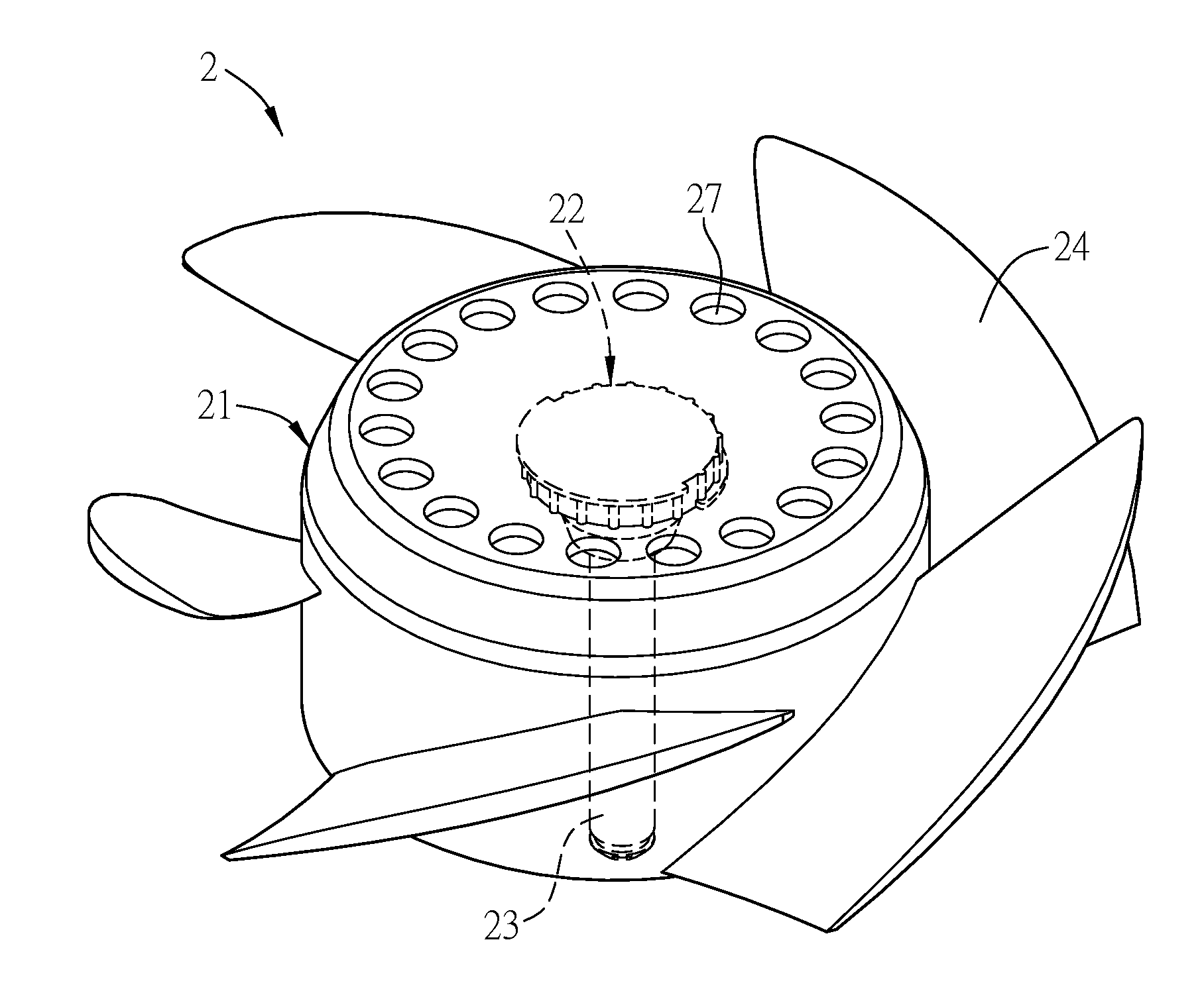
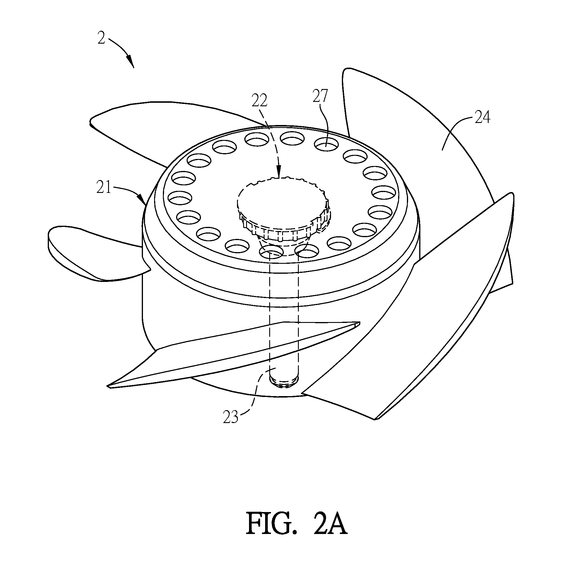
[0040]FIG. 2A is a schematic diagram of a rotor structure according to an embodiment of the invention, and FIG. 2B is a sectional diagram of the rotor structure in FIG. 2A. As shown in FIGS. 2A and 2B, a rotor structure 2 of a fan includes a hub 21, a bushing 22, a shaft 23 and a plurality of blades 24. The hub 21 includes a top portion 211 and at least a sidewall 212. The bushing 22 is connected to the top portion 211 of the hub 21. The top portion 211 of the hub 21 covers the bushing 22 in this embodiment, and the bushing 22 is disposed inside and fixed to the top portion 211. The hub 21 and the bushing 22 are made by the same material. One end 231 of the shaft 23 is connected to the bushing 22. The shaft 23 is disposed inside the top portion 211. The blades 24 are disposed on the p...


PUM


Abstract

A rotor structure of a fan includes a bushing, a hub, a shaft and a plurality of blades. The hub has a top portion and a sidewall, and the top portion of the hub covers the bushing. The hub and the bushing are made by the same material. One end of the shaft is connected to the bushing, and the shaft is disposed inside the top portion. The blades are disposed on the outer side of the sidewall of the hub. A manufacturing method of the rotor structure is also disclosed.

Description

CROSS REFERENCE TO RELATED APPLICATIONS[0001]This Non-provisional application claims priority under 35 U.S.C. §119(a) on Patent Application No(s). 201310398834.8 filed in People's Republic of China on Sep. 4, 2013, the entire contents of which are hereby incorporated by reference.BACKGROUND OF THE INVENTION[0002]1. Field of Invention[0003]The invention relates to a fan and a manufacturing method thereof and, in particular, to a rotor structure of a fan and a manufacturing method thereof.[0004]2. Related Art[0005]A rotor is commonly applied to a fan by a rivet bushing method. FIG. 1A is a schematic sectional diagram of a conventional rotor structure, and FIG. 1B is a flow chart of a manufacturing method of the conventional rotor structure. As shown in FIGS. 1A and 1B, the conventional rotor structure 1 includes a shaft 11, a magnetically permeable shell 12 and a copper bushing 13. The conventional manufacturing method includes the step S10 in which the shaft 11 and the copper bushing...

Claims


Application Information

Patent Timeline
IPC IPC(8): F04D29/05F04D29/60
CPCF04D29/60F04D29/05F04D29/263F05D2230/20F04D25/0613F04D19/002
Inventor HUANG, YUEH-LUNGLEE, CHIEN-MINGLIN, TINE-KUNLI, HAI-FENGHSIEH, MING-KAILEE, CHIEN-CHIH
Owner DELTA ELECTRONICS INC
Why Eureka
Try Eureka