Compliant constant velocity constant torque universal joint

a constant torque, universal joint technology, applied in the direction of yielding couplings, mechanical devices, couplings, etc., can solve the problems of non-constant velocity transfer function of hooke's universal joint, increased stress on the members of the universal joint, and potentially destructive vibration of the driven shaft. , to achieve the effect of simple mechanism construction

Inactive Publication Date: 2015-03-05
FLEXOUS
View PDF2 Cites 3 Cited by
  • Summary
  • Abstract
  • Description
  • Claims
  • Application Information

AI Technical Summary

Benefits of technology

The patent describes a universal joint that can transfer rotary movement between shafts with constant velocity and torque. The joint has a unique design that allows for a range of misalignment angles between 0° and 60°. The joint is simple in construction and can be fabricated from planar materials. These advantages make it easy to design and manufacture.

Problems solved by technology

However, Hooke's universal joint has a non-constant velocity transfer function.
As the angle between the two shafts increases, the variation in speed increases correspondingly, this causes increased stresses on the members of universal joint and a potentially destructive vibration on the driven shaft.
The rigid-body configuration has many disadvantages, such as wear, friction, backlash, being less cost effective and need for maintenance and assembling.
Besides, they are sometimes needed inside a vacuum or wet environment.
Therefore, it is difficult to use conventional bearings, due to the need of lubrication.
The backlash in rigid-body mechanical connections also can become a problem in high precision engineering.
However, all of them have a small misalignment angle, often less than 5°, and they cannot transmit rotation with constant torque due to large axial stiffness.
Moreover, the monolithic nature of flexible coupling and compliant design also gives rise to a drawback: the elastic deformation of the monolithic structure requires significant force and energy which is considered a ‘necessary evil’ in compliant mechanism designs.
In other words, the mechanical efficiency is poor, and it takes continuous force to hold the mechanism in position.

Method used


Image

  • Compliant constant velocity constant torque universal joint
  • Compliant constant velocity constant torque universal joint
  • Compliant constant velocity constant torque universal joint

Examples


Embodiment Construction

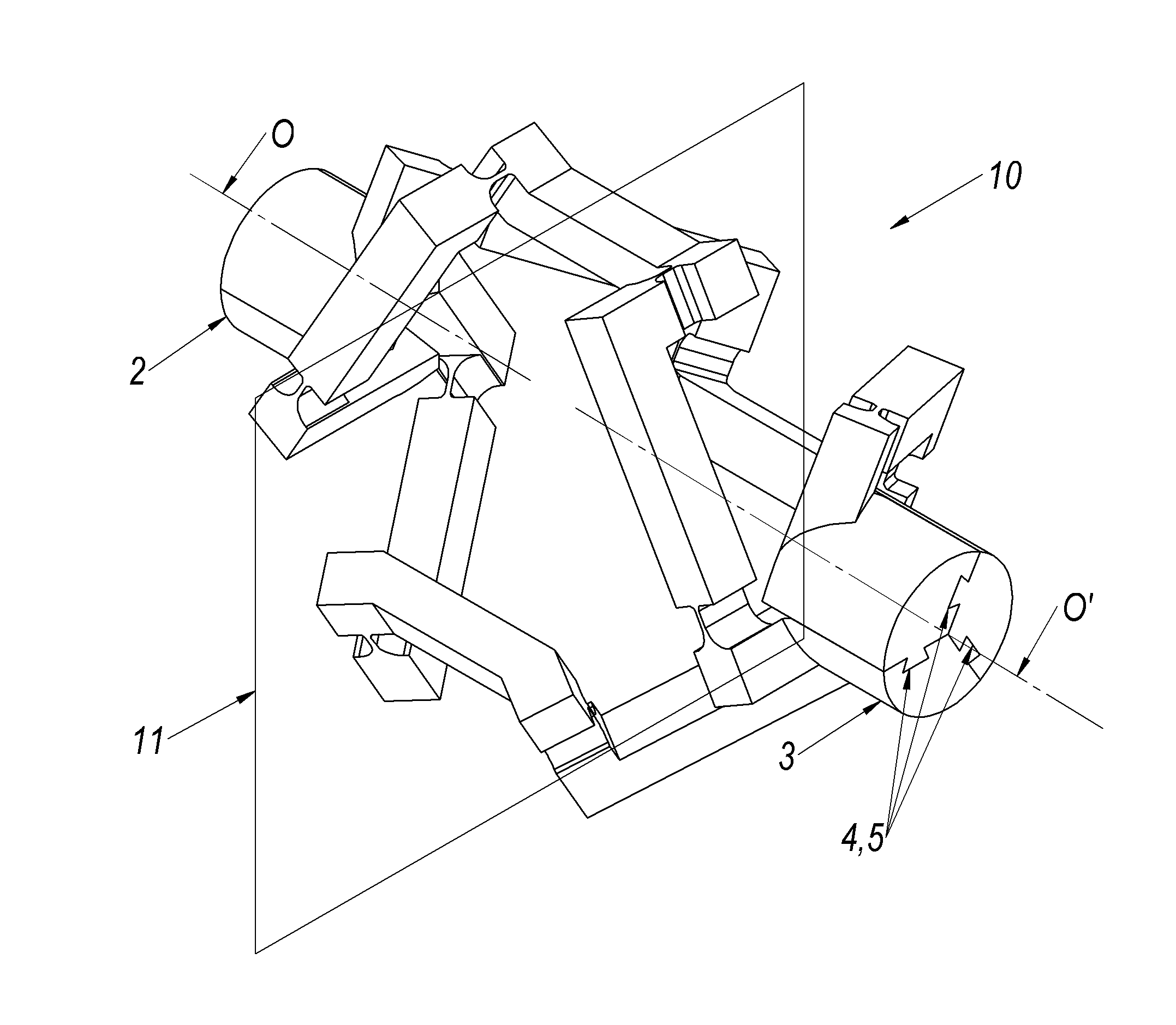
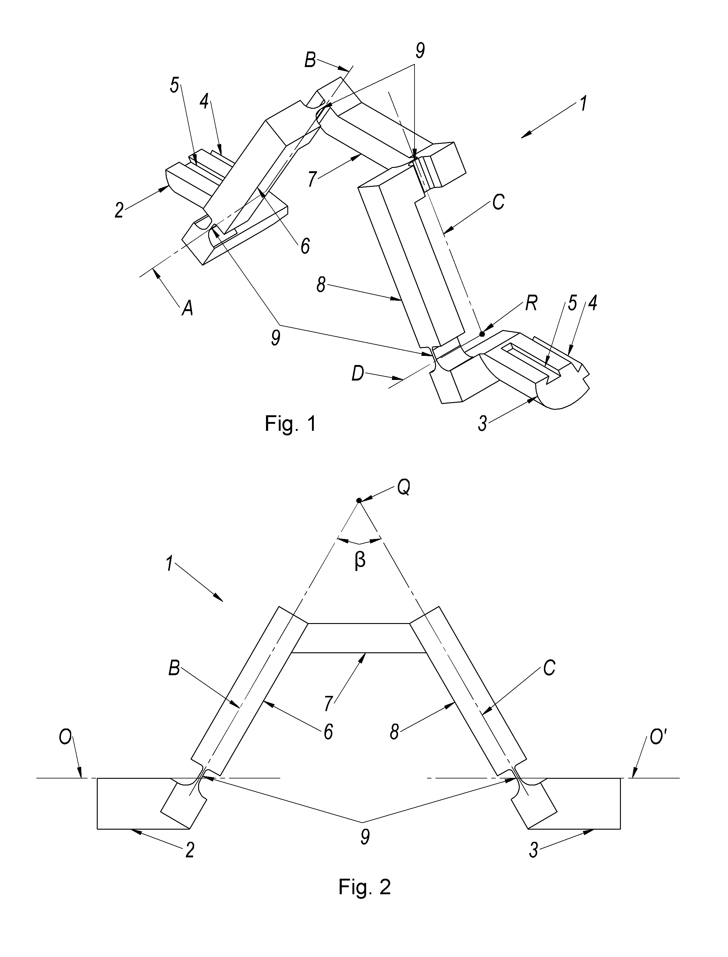
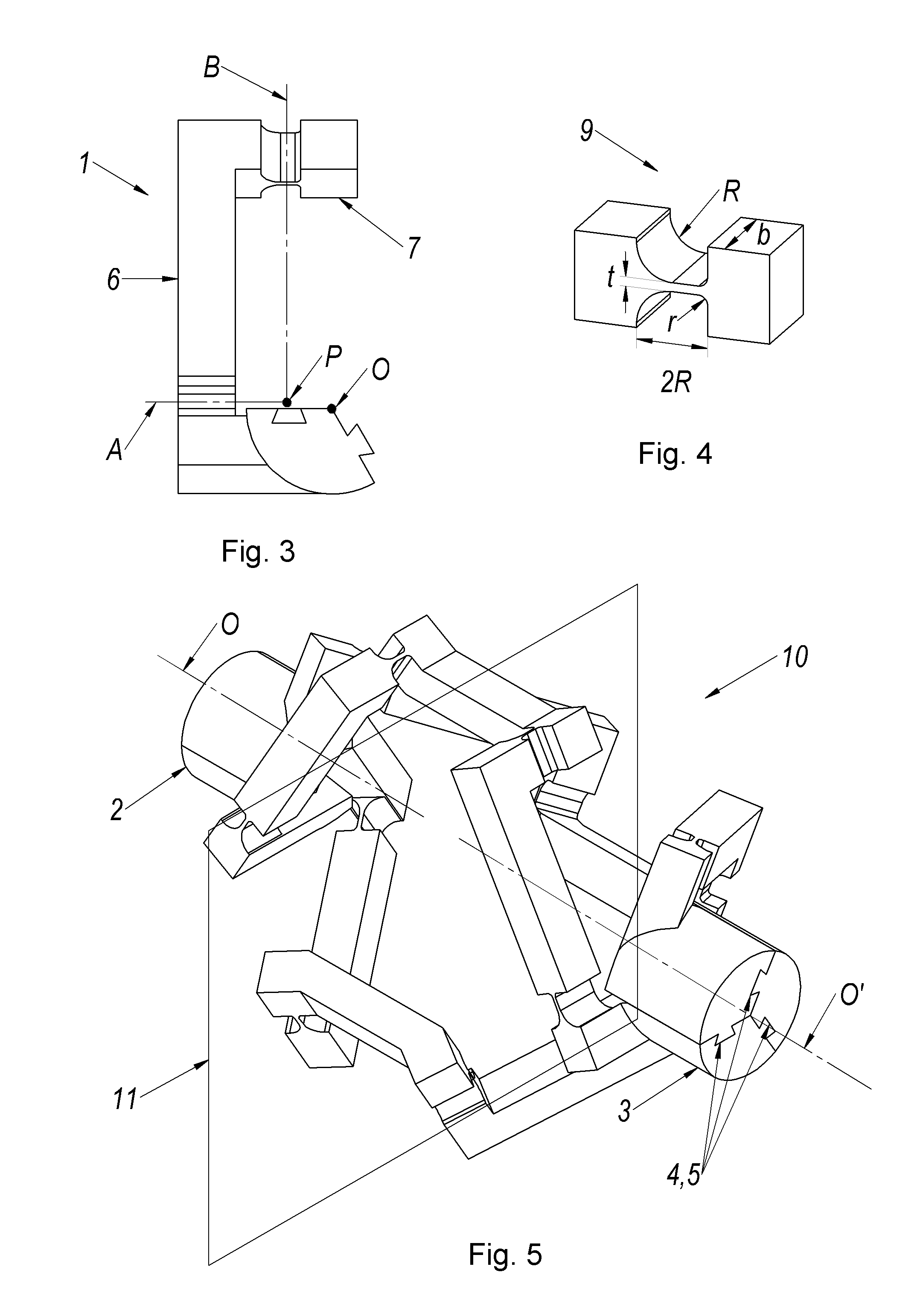
[0038]Reference will now be made to the drawings, wherein like numerals refer to like parts throughout. Referring to FIGS. 1-6, FIG. 1 illustrates one linkage 1 of a compliant constant velocity universal joint 10 which is shown in FIG. 5. As shown, the joint 10 includes a first independent link which can comprise a drive shaft 2 and a second independent link that can comprise—driven shaft 3. It will be apparent that while the linkage is described in conjunction with drive and driven shafts, the applicability of the current teachings can be applied between any two substantially rigid bodies. Pluralities of linkages 1 are assembled together in the manner shown in FIG. 5 to define the universal joint 10.

[0039]The drive shaft 2 is initially coupled to a cross link 40a that is attached to a crank link 6 via a first revolute joint 9a. The crank link 6 has a cross section 42a that is then connected to a coupler link 7 via a second revolute joint 9b. The coupler link 7 is then connected to ...


PUM


Abstract

A compliant constant velocity constant torque universal joint to transmit a rotary movement between two angled shafts, and / or a kinematic pair with two independent rotational degrees of freedom. This compliant structure is a large deflection compliant joint and the misalignment angle can be changed through the range of from 0° to 60°. The mechanism includes at least three compliant or statically balanced compliant spatial 4R (four revolute joint) linkages connected between two shafts, each system including four compliant joint axes and three rigid or compliant link members. The joint axes in each system are mounted so that each axis intersects one other joint axis. The compliant system is symmetrical about a plane which bisects two shaft axes perpendicularly.

Description

BACKGROUND OF THE INVENTION[0001]1. Field of the Invention[0002]The present invention relates to constant velocity universal joints and flexible coupling for joining the ends of rotatable shafts which are subject to axial misalignment to achieve a more constant angular velocity transfer between shafts. Moreover, it relates to multiple degrees of freedom joints which present at least two rotational degrees of freedom.[0003]2. Description of the Related Art[0004]Many applications require a mechanism to transmit rotation from one direction to another direction with constant velocity and constant torque. The primitive and traditional method to solve the problem of rotation transmission was Hooke's universal joint. A Hooke's universal joint includes three similar sets of four-bar spherical linkages which move in synchrony. However, Hooke's universal joint has a non-constant velocity transfer function. As the angle between the two shafts increases, the variation in speed increases corresp...

Claims


Application Information

Patent Timeline
Patent Type & Authority Applications(United States)
IPC IPC(8): F16D3/10
CPCF16D3/10F16D3/005F16D3/40F16D3/30F16D3/32F16D3/16
Inventor MACHEKPOSHTI, DAVOOD FARHADITOLOU, NIMA
Owner FLEXOUS
Why Eureka
Try Eureka