Detachment mechanisms for implantable devices

a technology of detachment mechanism and implantable device, which is applied in the field of detachment mechanism, can solve the problems of rupture or dissection, bleeding among the layers of the arterial wall, and the need for an external energy sour

Active Publication Date: 2015-03-05
MA JIANLU
View PDF11 Cites 16 Cited by
  • Summary
  • Abstract
  • Description
  • Claims
  • Application Information

AI Technical Summary

Benefits of technology

[0023]The schematic flow chart diagrams included herein are generally set forth as logical flow chart diagrams. As such, the depicted order and labeled steps are indicative of one embodiment of the presented method. Other steps and methods may be conceived that are equivalent in function, logic, or effect to one or more steps, or portions thereof, of the illustrated method. Additionally, the format and symbols employed are provided to explain the logical steps of the method and are understood not to limit the scope of the method...

Problems solved by technology

When an aneurysm grows large, it may rupture or dissect.
Rupture causes internal bleeding through the aneurysm into the body, and dissection splits the tissue layers forming the artery and causes bleeding among the layers of the arterial wall.
Aortic and cerebral aneurysms if allowed to rupture/dissect can cause serious complications and are often fatal, particularly aortic aneurysms which have about 10-25% post-rupture survival rate.
There are several drawbacks to using an external energy source to sever the sacrificial joint and detach the vaso-occlusion device.
The first drawback is the need for an external energy source itself.
The vessel at the location of the aneurysm is already weakened, and the application of external las...

Method used


Image

  • Detachment mechanisms for implantable devices
  • Detachment mechanisms for implantable devices
  • Detachment mechanisms for implantable devices

Examples


Embodiment Construction

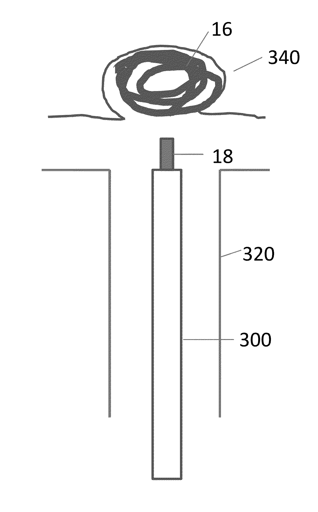
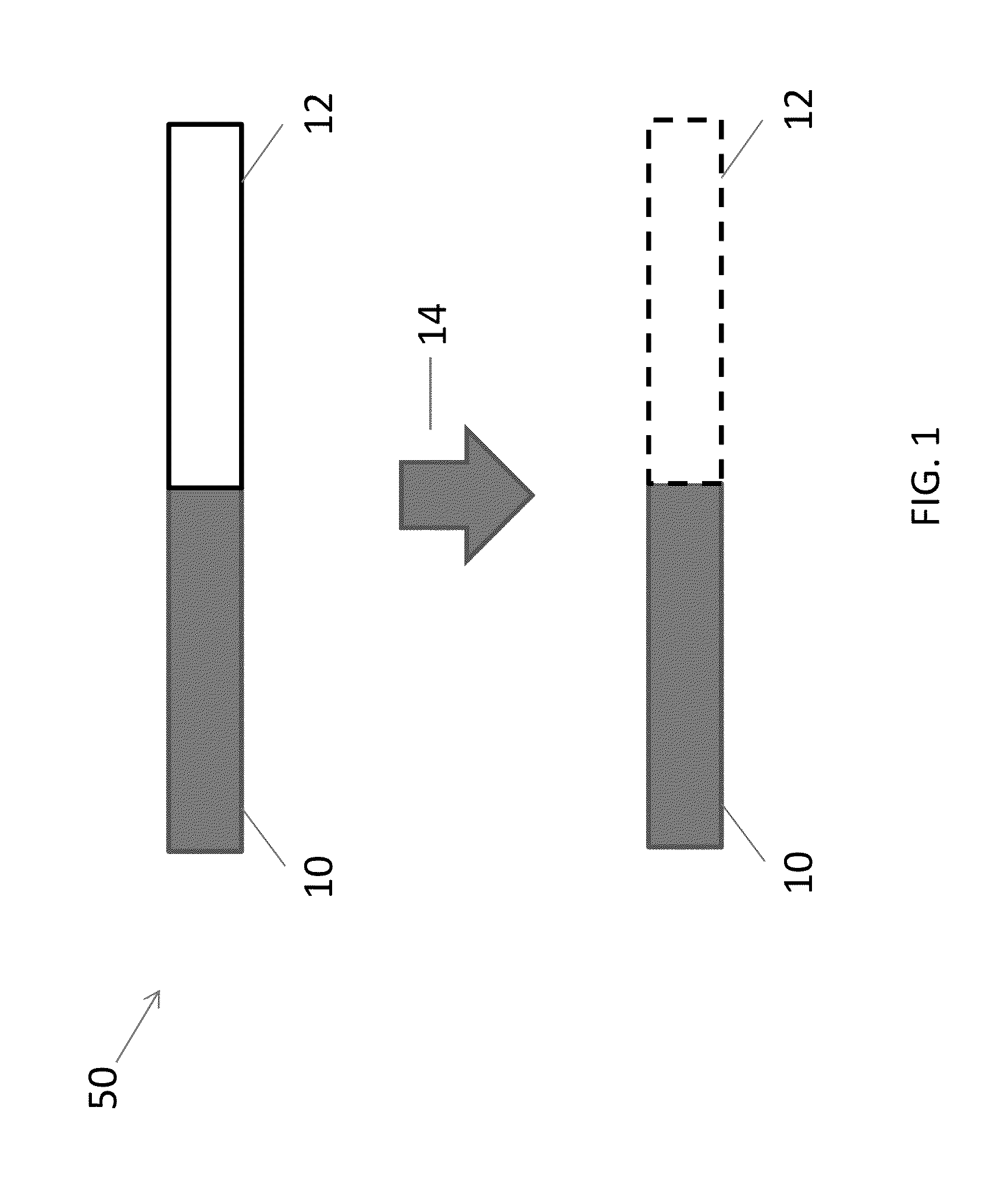
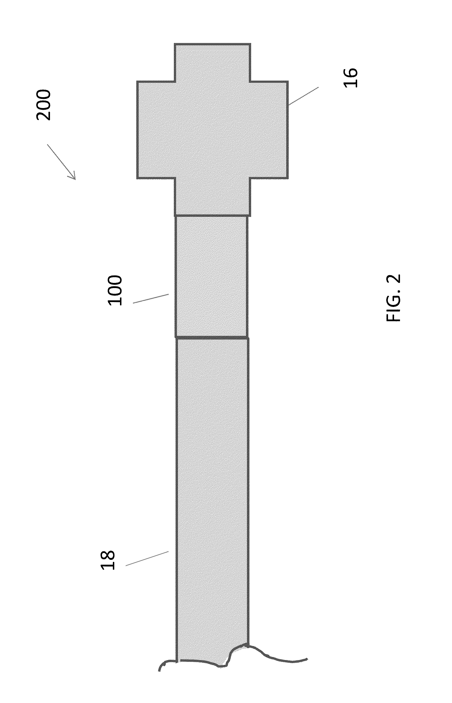
[0033]The present invention provides systems and related methods for detaching an implantable device from a delivery member without application of an external energy source. Aspects of the invention are accomplished by using a junction that decouples an implant from a delivery device based on galvanic corrosion. According to certain embodiments, the junction includes an anodic metal coupled to a cathodic metal such that the anodic metal galvanically corrodes when the junction is exposed to an electrolytic fluid. The degradation of the anodic metal causes the implant to detach at target implantation site and allows unhindered removal of the delivery device from the body lumen. A benefit of the present invention is that the corrosion of the junction and detachment of the implant occur without application energy from an external energy source. Aspects of the systems and methods of the invention, including galvanically-corrodible junctions, delivery devices, and implants, are described ...


PUM


Abstract

The present invention relates to detachment mechanisms for delivering and releasing implantable devices into a body lumen. According to certain aspects, systems of the invention include a junction that couples an implantable device to a delivery member. The junction includes an anodic portion and a cathodic portion galvanically coupled to the anodic portion such that the anodic portion corrodes when exposed to an electrolytic fluid, thereby detaching the implantable device from the delivery member without application of energy from an external power source.

Description

CROSS REFERENCE TO RELATED APPLICATIONS[0001]This application claims the benefit of and priority to U.S. Patent Provisional Application No. 61 / 872,861 filed on Sep. 3, 2013, the entirety of which is incorporated by reference herein.TECHNICAL FIELD[0002]The present invention relates to detachment mechanisms for delivering and releasing implantable devices into a body lumen.BACKGROUND OF THE INVENTION[0003]An aneurysm is a sac or balloon-like bulge formed in the wall of a blood vessel. Typically, aneurysms are formed in arteries, the blood vessels that carry oxygen-rich blood from the heart throughout the body and its organs. Formation of aneurysms occur when arteries are unable to withstand the pressure of normal blood flow due to weakened or injured arterial walls, e.g. caused by cardiovascular disease, genetic conditions, and trauma. When an aneurysm grows large, it may rupture or dissect. Rupture causes internal bleeding through the aneurysm into the body, and dissection splits th...

Claims


Application Information

Patent Timeline
IPC IPC(8): A61B17/12
CPCA61B17/12113A61B2017/12063A61B17/12022A61B17/1214
Inventor MA, JIANLU
Owner MA JIANLU
Why Eureka
Try Eureka