Time slot protocol

a time slot and protocol technology, applied in the field of computing networks, can solve the problems of inconsistent system cost, impracticality of point-to-point connection, and ethernet, but suffer from being unpredictable regarding the timely delivery of periodic data, so as to increase the utilization of the bus and increase the bandwidth for payload.

Active Publication Date: 2009-02-03
SMITHS AEROSPACE INC
View PDF20 Cites 15 Cited by
  • Summary
  • Abstract
  • Description
  • Claims
  • Application Information

AI Technical Summary

Benefits of technology

[0014]In one aspect of the present invention, a method of operating a network is provided. The network includes a plurality of devices connected to a shared bus of the network. The method involves transmitting an epoch packet indicative of the beginning of each frame. The epoch packet thus comprises timing information. In addition, the epoch packet has a table including (i) time slot assignments for devices on the bus, (ii) a time slot offset for each time slot assignment, and (iii) a time slot duration for each time slot assignment. The frames are repeated over and over. The method further involves controlling access to the bus during the assigned one or more time slots using the time slot offset and duration data.
[0015]In another aspect of the present invention, an additional step involves assigning to each time slot no more than one of the plurality of the devices within a collision domain. The assignments indicate the identity of the device permitted to transmit packets onto the bus during the assigned time slot(s). A further step involves defining the above-mentioned table that includes such time slot assignments, and time slot offset and time slot duration data for each time slot. A still further step involves broadcasting the table over the bus to each of the plurality of devices in the epoch packet. Each device is configured to determine its transmission time based on its assigned time slot, offset, and slot duration, all taken from the table. The transmiss

Problems solved by technology

However, with increasing complexity of real-time systems, the use of point-to-point connections becomes impractical, because the number of interconnections becomes unwieldy.
Exacerbating the problem is the fact that point-to-point buses use separate transmit and receive media, and quite often require redundancy to ensure availability.
Such an approach results in an architecture that creates a “cobweb” of wiring, with devices that require an increased number of parts, both factors driving the cost of a system consistent with such an approach in an upward spiral.
Ethernet, however, suffers from being unpredictable regarding the timely delivery of periodic data.
This drawback is due in part to the lack of control on when a device on the network can transmit, and, the method defined by the Ethernet standard to resolve contention for the bus.
Collisions on the bus between two or more devices seeking to transmit at the same time may result in potentially high time latencies for the data sought to be transmitted by stations on the bus.
While such high latencies may be tolerated for basic computer data, which in general may comprise asynchronous data, such characteristics are unacceptable for real-time embedded control systems that require communication of data between system elements in a methodical, deterministic fashion to perform the intended real-time tasks.
A problem with the system proposed in Gross et al. relates to the synchronization scheme.
The resulting timing uncertainty and undesirably large amounts of jitter may affect the performance of the system disclosed in Gross et al.
While such performance shortcomings may be tolerated from time-to-time when the payload being carried involves audio and/or video data, such shortcomings a

Method used


Image

  • Time slot protocol
  • Time slot protocol
  • Time slot protocol

Examples


Embodiment Construction

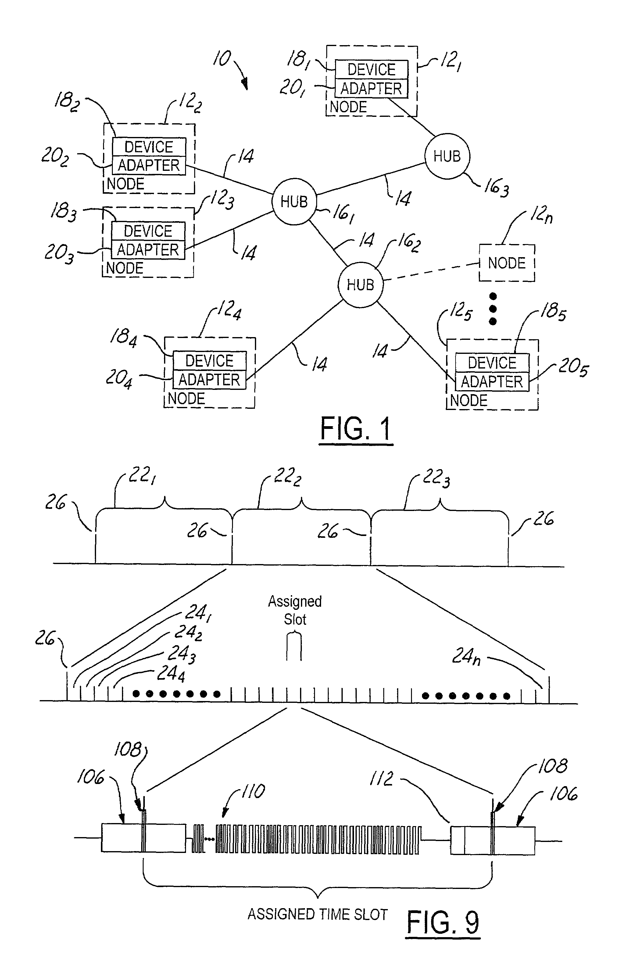
[0029]Referring now to the drawings wherein like reference numerals are used to identify identical components in the various views, FIG. 1 is a block diagram view of a network 10 according to the invention. The present invention may be implemented over a wide variety of networks and shared media or bus types, and will be described in connection with a preferred embodiment implemented over an Ethernet network. It should be understood, however, that the present invention is not limited to an Ethernet network and further is not limited to a Carrier Sense Multiple Access (CSMA) with Collision Detection (CD) access protocol. The present invention may be usefully deployed for a wide variety of applications, and is particularly suited for real-time embedded control applications where strict deterministic access to the network, and low jitter, are required. In one embodiment, network 10 may be an avionics communications network.

[0030]As shown in FIG. 1, network 10 includes a plurality of no...


PUM


Abstract

A computing network uses Time Division Multiplexing (TDM) to divide the time on a bus into a plurality of frames, each frame having a plurality of time slots. Each time slot is assigned no more than one of the plurality of devices within a collision domain, the assignments indicating the identity of the device permitted to transmit packets onto the network during the assigned time slot. A bus cadence unit simultaneously sends an epoch packet initiating the frame. The epoch packet contains a time slot assignment table containing the time slot assignments, the device identification, as well as a time slot offset and duration. Each device on the network is configured to measure a frame interval between repeating epoch packets. The measured frame interval is further processed in each receiving node to obtain a calibrated frame interval. The calibrated frame interval is used to accurately synchronize transmissions of data from the various devices onto the network. A time slot protocol governor in each node controls access to the bus to only the assigned time slot or slots using the calibrated frame interval to reduce or eliminate synchronization errors.

Description

RELATED APPLICATIONS[0001]This application claims the benefit of U.S. provisional application Ser. No. 60 / 340,614 filed Dec. 14, 2001, hereby incorporated by reference in its entirety.BACKGROUND OF THE INVENTION[0002]1. Technical Field[0003]This invention relates generally to computing networks and, more particularly, to a system and method for a time slot protocol for such computing networks.[0004]2. Description of the Related Art[0005]It is known for real-time systems to utilize point-to-point data buses to ensure that data delivery is deterministic with low jitter. However, with increasing complexity of real-time systems, the use of point-to-point connections becomes impractical, because the number of interconnections becomes unwieldy. Exacerbating the problem is the fact that point-to-point buses use separate transmit and receive media, and quite often require redundancy to ensure availability. Such an approach results in an architecture that creates a “cobweb” of wiring, with d...

Claims


Application Information

Patent Timeline
IPC IPC(8): H04J3/16H04L12/40H04L12/403H04L29/06
CPCH04L12/4035H04L69/28H04L2012/4028
Inventor WALTER, RANDY L.SCHROEDER, JOHN L.VANBAREN, GERALD W.HODGES, DONALD G.ALBERS, COURTNEY L.
Owner SMITHS AEROSPACE INC
Why Eureka
Try Eureka