Magnetic shielding apparatus and magnetic shielding method

a magnetic shielding and magnetic shielding technology, applied in active shielding, instruments, transmission, etc., can solve the problems of difficult noise in the external magnetic field of highly sensitive magnetic field measurement, and the inability to create an environment where a magnetic field gradient can be reduced, so as to reduce the manufacturing cost

Active Publication Date: 2015-03-12
SEIKO EPSON CORP
View PDF2 Cites 10 Cited by
  • Summary
  • Abstract
  • Description
  • Claims
  • Application Information

AI Technical Summary

Benefits of technology

[0115](2) For making the magnetic field strength of the correction target space 150 equal to or less than the threshold value, the magnetic field strength can be controlled using the publicly known Helmholtz coil as the internal coils 13A and 13B. That is, with the internal coils 13A and 13B that are easily available, the correction target space 150 can be made into a substantially zero magnetic field, so that minute magnetic signals from, for example, the heart or brain can be measured at a high SN ratio.
[0116](3) It is sufficient that the first magnetic sensor 14A and the second magnetic sensor 14B have the measurement sensitivity at about the same level. They do not need to be, for example, a highly sensitive sensor (for example, an optical pumping magnetic sensor) (not shown) arranged in the correction target space 150. Accordingly, the magnetic shielding apparatus 100 with reduced manufacturing cost can be provided.
[0117]The invention is not limited to the embodiment described above, and various embodiments are possible. Some modified examples will be described below. A description of portions overlapping the portions described in the embodiment is omitted.

Problems solved by technology

Therefore, such an external magnetic field becomes noise in highly sensitive magnetic field measurement.
However, in the techniques disclosed in Patent Document 1 to Patent Document 8, there is a problem that it is difficult to create an environment where a magnetic field gradient is extremely gentle in the interior of a magnetic shield.
Specifically, a magnetic field from the outside can be reduced in the related art; however, there is a problem that a gradient is generated in the magnetic field state of the interior of the magnetic shield because a magnetization component or the like of the magnetic shield is not considered.

Method used


Image

  • Magnetic shielding apparatus and magnetic shielding method
  • Magnetic shielding apparatus and magnetic shielding method
  • Magnetic shielding apparatus and magnetic shielding method

Examples


embodiment

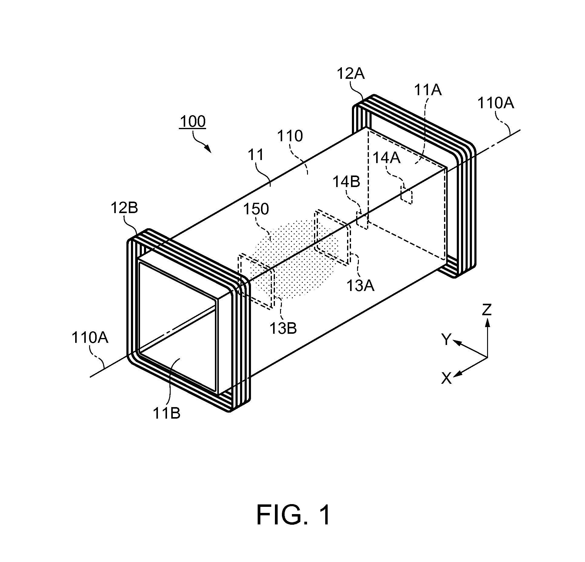
[0042]FIG. 1 is a perspective overview of a magnetic shielding apparatus 100 according to the embodiment. The magnetic shielding apparatus 100 is used to shield a magnetic measuring device from an external magnetic field such as terrestrial magnetism when, for example, measuring a weak current generated from a living body as magnetism.

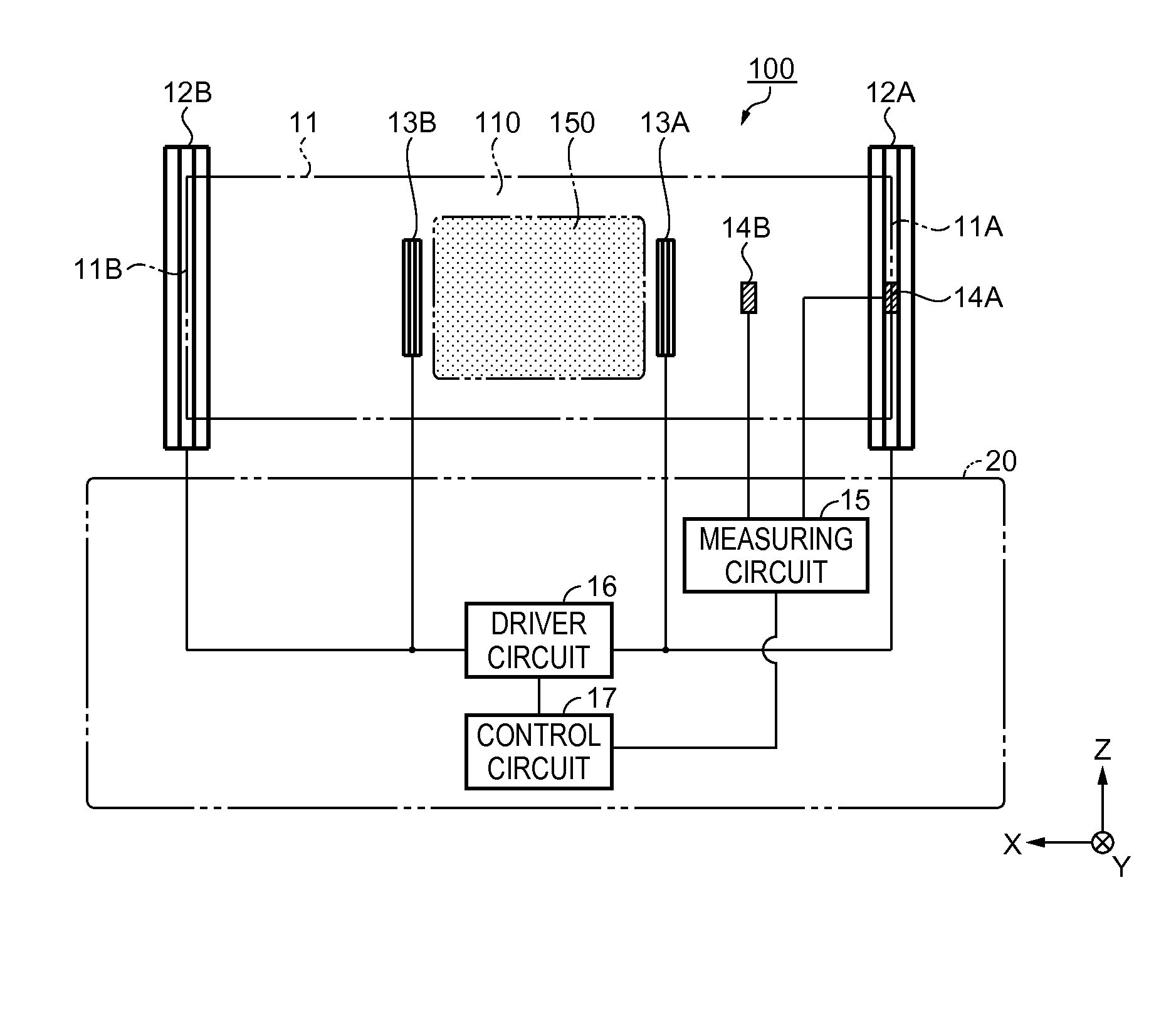
[0043]The magnetic shielding apparatus 100 includes a passive shield 11, external coils 12A and 12B that correct an internal magnetic field of the passive shield 11, a first magnetic sensor 14A, a second magnetic sensor 14B, internal coils 13A and 13B that are arranged in the interior of the passive shield 11, and a control unit 20 (refer to FIG. 2). The external coils 12A and 12B are an example of a “first coil” according to the invention, and the internal coils 13A and 13B are an example of a “second coil” according to the invention.

[0044]The passive shield 11 has a cylindrical shape with a cavity therein, and is arranged on, for example, a base (not...

modified example 1

Arrangement Examples of Magnetic Sensors

[0118]The arrangement of the first magnetic sensor 14A and the like for measuring a magnetic field strength is not limited to that shown in FIG. 2. Some arrangements of the first magnetic sensor 14A and the like will be described below.

[0119]FIG. 6 is an overview of a magnetic shielding apparatus 200, showing a second arrangement example. In this example, only one external coil 12A is driven, and the other external coil 12B is not driven. Therefore, the control of the inflowing magnetic field gradient performed by the control circuit 17 can be simplified.

[0120]FIG. 7 is an overview of a magnetic shielding apparatus 300, showing a third arrangement example. In this example, two sets of magnetic sensors are provided: one set is for measuring the inflowing magnetic field into the passive shield 11 and the other set for measuring the magnetic field of the interior space 110. First magnetic sensors 14A and 14C are magnetic sensors for measuring the...

modified example 2

[0126]The cross-sectional shape of the passive shield 11 in the X-direction is not limited to that described in the embodiment. For example, the cross-sectional shape may be polygonal or circular, or may be a shape combining a straight line with a curve at the periphery. Specifically, the cross-sectional shape of the passive shield 11 may be a circle or an ellipse, and in addition, may be a quadrilateral shape, a pentagonal shape, a hexagonal shape, a heptagonal shape, an octagonal shape, and the like in the case of a polygon.

[0127]Moreover, the passive shield 11 may not include the openings 11A and 11B, or may include only one of the openings 11A and 11B. Alternatively, the openings 11A and 11B are covered with lids or the like. By providing flexibility in the shape of the passive shield 11, the magnetic shielding apparatus 100 can be applied to various magnetic measuring devices.


PUM


Abstract

A magnetic shielding apparatus includes: a passive shield; a correction target space that is defined in the interior of the passive shield; external coils as a first coil that corrects a magnetic field in the passive shield; a first magnetic sensor; a second magnetic sensor that is arranged more inside the passive shield than the first magnetic sensor; and a control unit. The first magnetic sensor and the second magnetic sensor measure a magnetic field gradient in the passive shield. The control unit controls the external coils based on a result of the measurement performed by the first magnetic sensor and the second magnetic sensor.

Description

[0001]This application claims the benefit of Japanese Patent Application No. 2013-188097, filed on Sep. 11, 2013, and Japanese Patent Application No. 2014-127008, filed on Jun. 20, 2014. The contents of the aforementioned applications are incorporated herein by reference in their entirety.BACKGROUND[0002]1. Technical Field[0003]The present invention relates to a magnetic shielding apparatus and a magnetic shielding method.[0004]2. Related Art[0005]Diagnostic imaging is widely used in medical practice. The diagnostic imaging, which is non-invasive and therefore puts less burden on the human body, is preferably used especially in examining organs important for the vital activities, such as the heart or brain.[0006]The organs of a living body always generate weak currents due to the activities of neurons. By measuring magnetic fields caused by the currents, the condition of the organ can be known.[0007]Specifically, the magnetic field arising from the living body is extremely weak such...

Claims


Application Information

Patent Timeline
Patent Type & Authority Applications(United States)
IPC IPC(8): H05K9/00G01R1/18
CPCG01R1/18H05K9/0071G01R33/0076G01R33/025
Inventor HOKARI, RYUJI
Owner SEIKO EPSON CORP
Why Eureka
Try Eureka