Structural Health Monitoring System for a Material and Production Method

Active Publication Date: 2015-03-12
AIRBUS DEFENCE & SPACE
View PDF13 Cites 9 Cited by
  • Summary
  • Abstract
  • Description
  • Claims
  • Application Information

AI Technical Summary

Benefits of technology

[0044]This embodiment enables a detection of the damage

Problems solved by technology

If structural health monitoring systems are applied to a material as additional applications, then the result may be an additional weight, which may be undesired, depending on the field of application of the material.
In the case of ultrasound heads, which are adhesively cemented on a material, the bonding joint may form, for example, a weak point, especially if sign

Method used


Image

  • Structural Health Monitoring System for a Material and Production Method
  • Structural Health Monitoring System for a Material and Production Method
  • Structural Health Monitoring System for a Material and Production Method

Examples


Embodiment Construction

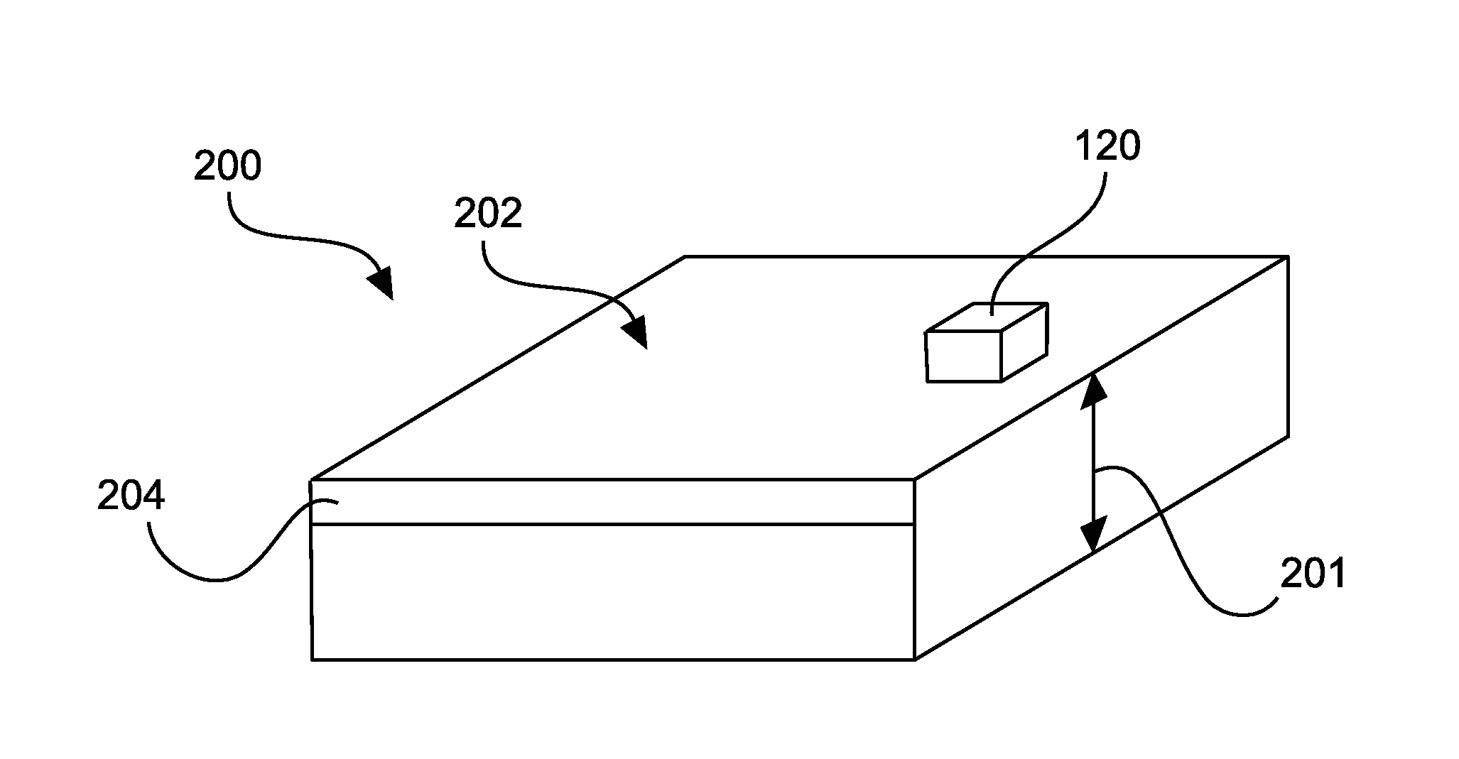
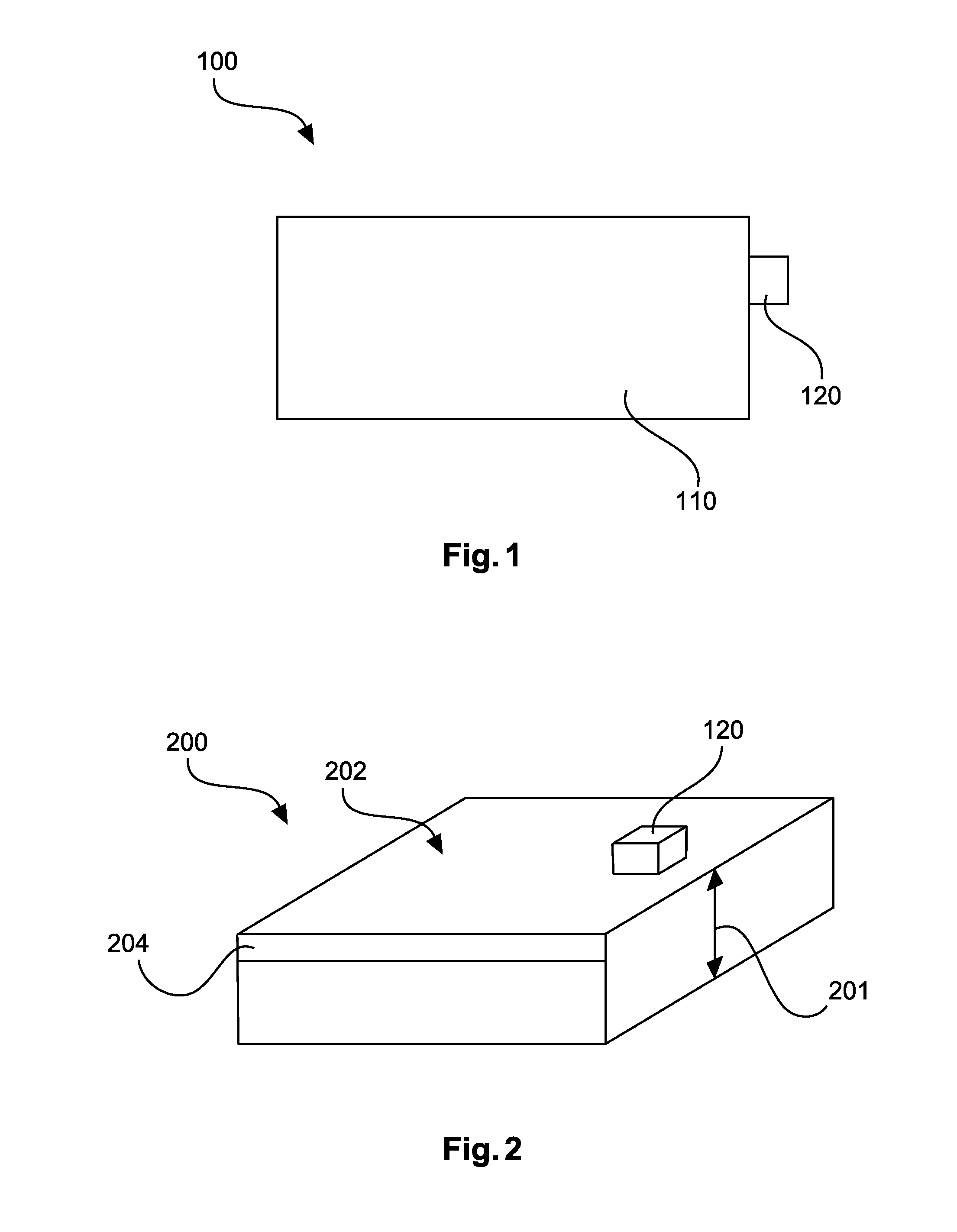
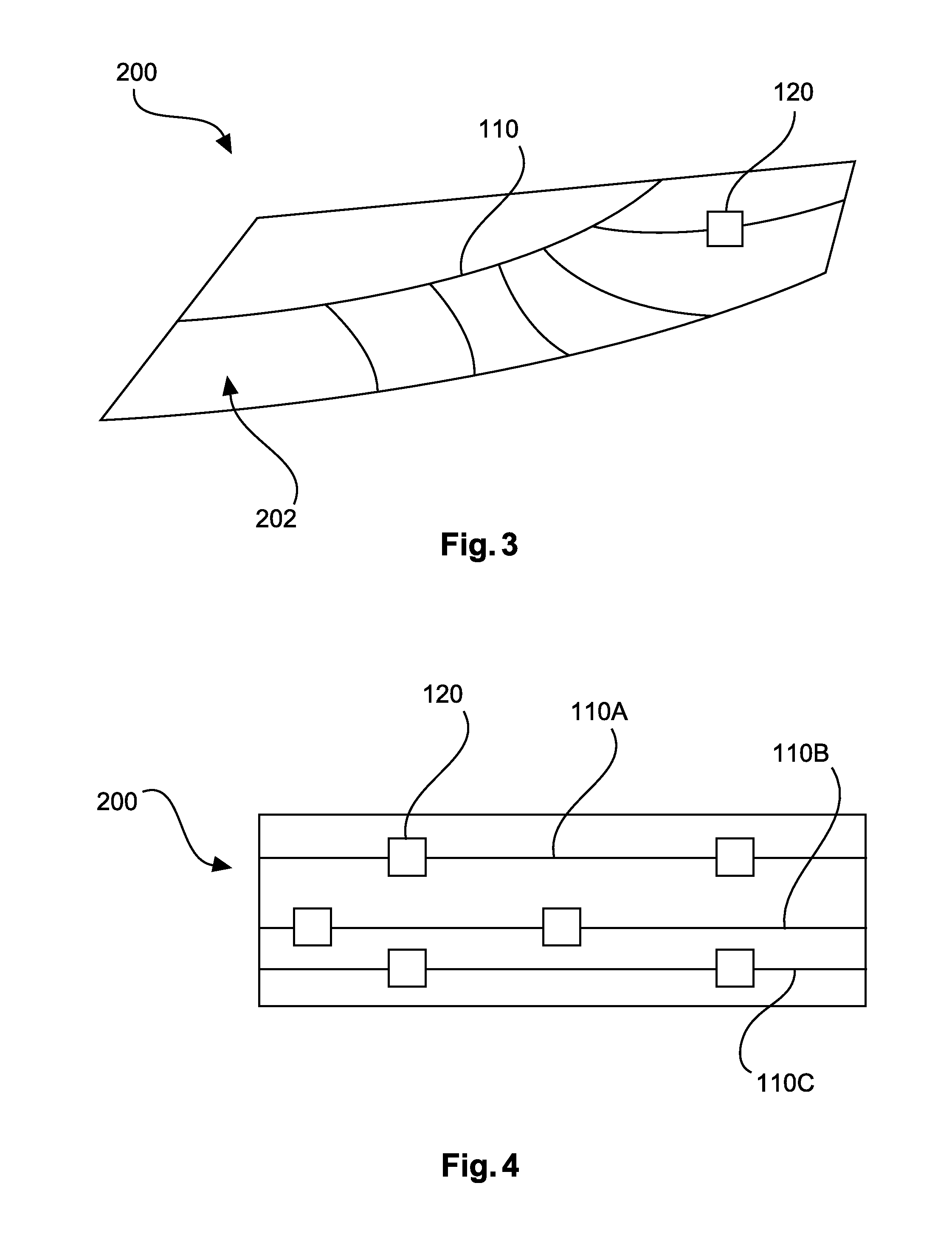
[0064]FIG. 1 shows a structural health monitoring system 100 comprising a signal transmission element 110 and a sensor element 120. The sensor element 120 is coupled to the signal transmission element 110, so that at least one electrical signal and / or one thermal signal can be fed into the signal transmission element 110 and can be read out of the signal transmission element. For this purpose the signal is fed in and read out at different locations, so that the signal transmission element acts with the transmission function on the signal that is fed in.

[0065]Changes in the structure of the signal transmission element 110 cause a change in the transmission function, so that these structural changes can be detected.

[0066]In FIG. 1 the signal transmission element is shown as a flat element, which can be applied, for example, to a surface of a material.

[0067]As an alternative, the signal transmission element can also have a plurality of lines or line sections, which are connected to eac...


PUM


Abstract

A structural health monitoring system includes a signal transmission element and a sensor unit. The sensor unit is designed to feed a first signal into the signal transmission element and to read out a second signal from the signal transmission element. The signal transmission element has carbon nanotubes.

Description

CROSS-REFERENCE TO RELATED APPLICATIONS[0001]The present application claim priority under 35 U.S.C. §119 to German application 10 2013 014 822.7, filed Sep. 10, 2013, the entire disclosure of which is herein expressly incorporated by reference.FIELD OF THE INVENTION[0002]Exemplary embodiments of the invention relate to a structural health monitoring system for a material, a material with a structural health monitoring system as well as a method for producing such a material.BACKGROUND OF THE INVENTION[0003]The properties of materials, which are used in a complex, higher level overall structure, can be subject to monitoring, for example, in order to obtain a periodically recurrent overview of the properties of the monitored material. In particular, the mechanical and physical properties of a material, for example, the strength, residual strength, fatigue, E-modulus, are the target of such structural health monitoring measures.[0004]Structural health monitoring systems are used to mon...

Claims


Application Information

Patent Timeline
IPC IPC(8): G01N25/72
CPCG01N25/72G01M5/0016G01M5/0025G01M5/0033G01M5/0083G01L19/0007G01F1/68B64G1/56G01R31/08G01M9/065
Inventor LENCZOWSKI, BLANKA
Owner AIRBUS DEFENCE & SPACE
Why Eureka
Try Eureka