Device for Loading Porous Substrates of Three-Dimensional Shape in Order to be Densified by Directed Flow Chemical Vapor Infiltration

a three-dimensional shape, directed flow technology, applied in the direction of chemical vapor deposition coating, metallic material coating process, coating, etc., can solve the problems of not being able to meet the requirements of densification substrates, and not being able to achieve uniform densification of substrates. achieve the effect of minimizing densification gradients and high loading capacity

Active Publication Date: 2015-03-19
SAFRAN CERAMICS SA
View PDF6 Cites 3 Cited by
  • Summary
  • Abstract
  • Description
  • Claims
  • Application Information

AI Technical Summary

Benefits of technology

[0008]An object of the invention is to provide a loading solution that enables porous substrates to be densified, in particular thin substrates of complex three-dimensional shape extending mainly in a longitudinal direction, with a high loading capacity, and to do so while minimizing densification gradients in the substrates.
[0014]The loader device of the invention makes it possible to optimize the number of substrates that can be densified simultaneously in a given installation while simultaneously controlling the flow direction of the reagent gas in each substrate so as to densify it uniformly. Such densification in large numbers cannot be obtained with substrates that are as close to one another as when the flow is not directed.
[0015]Consequently, the method of the invention makes it possible to densify thin porous substrates, and to do so while increasing both the quality of the parts that are obtained and also the volume of the reaction chamber that is loaded.
[0016]Once the loader device of the invention has been placed in a reaction chamber, it acts as a mini-reactor in which the flow of gas is under control. With this device, a load of substrates can be prepared in advance away from the densification installation, and can be transported easily without risk to the reaction chamber. This serves to reduce the time required for loading and unloading chambers.

Problems solved by technology

Nevertheless, those methods relate essentially to densifying substrates of annular shape arranged in stacks and they are not suitable for densifying substrates that present shapes that are not axisymmetric.
Nevertheless, that loader tooling remains limited to directed flow densification of substrates that are thin and simple in shape such as thin rectangular plates, and it does not make it possible to obtain uniform densification of substrates that are of complex three-dimensional shape such as fiber preforms for blades.
The flow of a gas stream over substrates that are of complex three-dimensional shape is more difficult to control.
The lack of control over the flow of the reagent gas over the set of substrates to be densified leads to the appearance of densification gradients in the substrates.

Method used


Image

  • Device for Loading Porous Substrates of Three-Dimensional Shape in Order to be Densified by Directed Flow Chemical Vapor Infiltration
  • Device for Loading Porous Substrates of Three-Dimensional Shape in Order to be Densified by Directed Flow Chemical Vapor Infiltration
  • Device for Loading Porous Substrates of Three-Dimensional Shape in Order to be Densified by Directed Flow Chemical Vapor Infiltration

Examples


Embodiment Construction

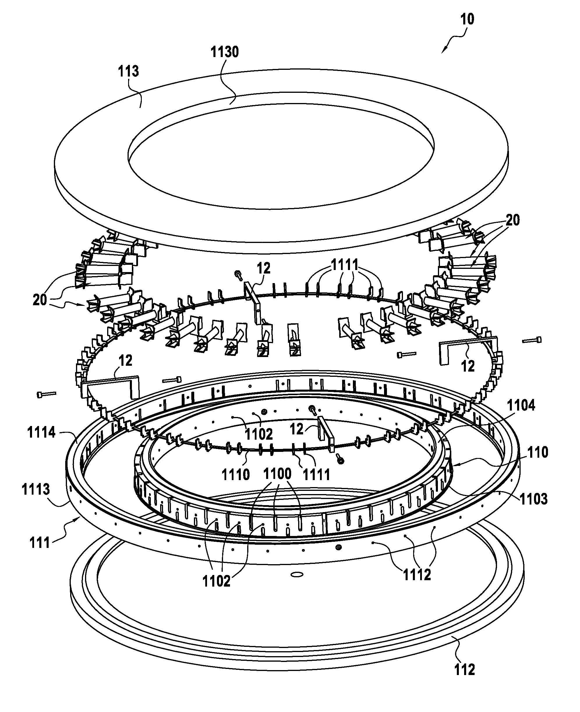
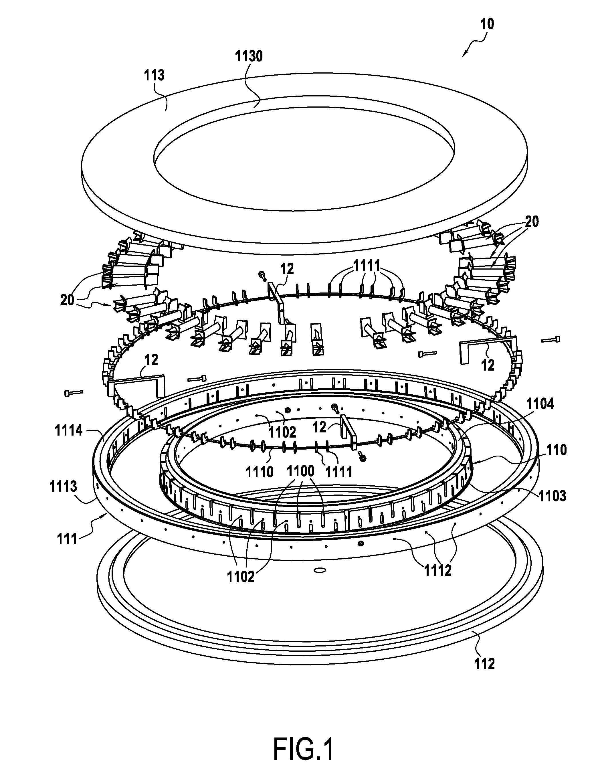
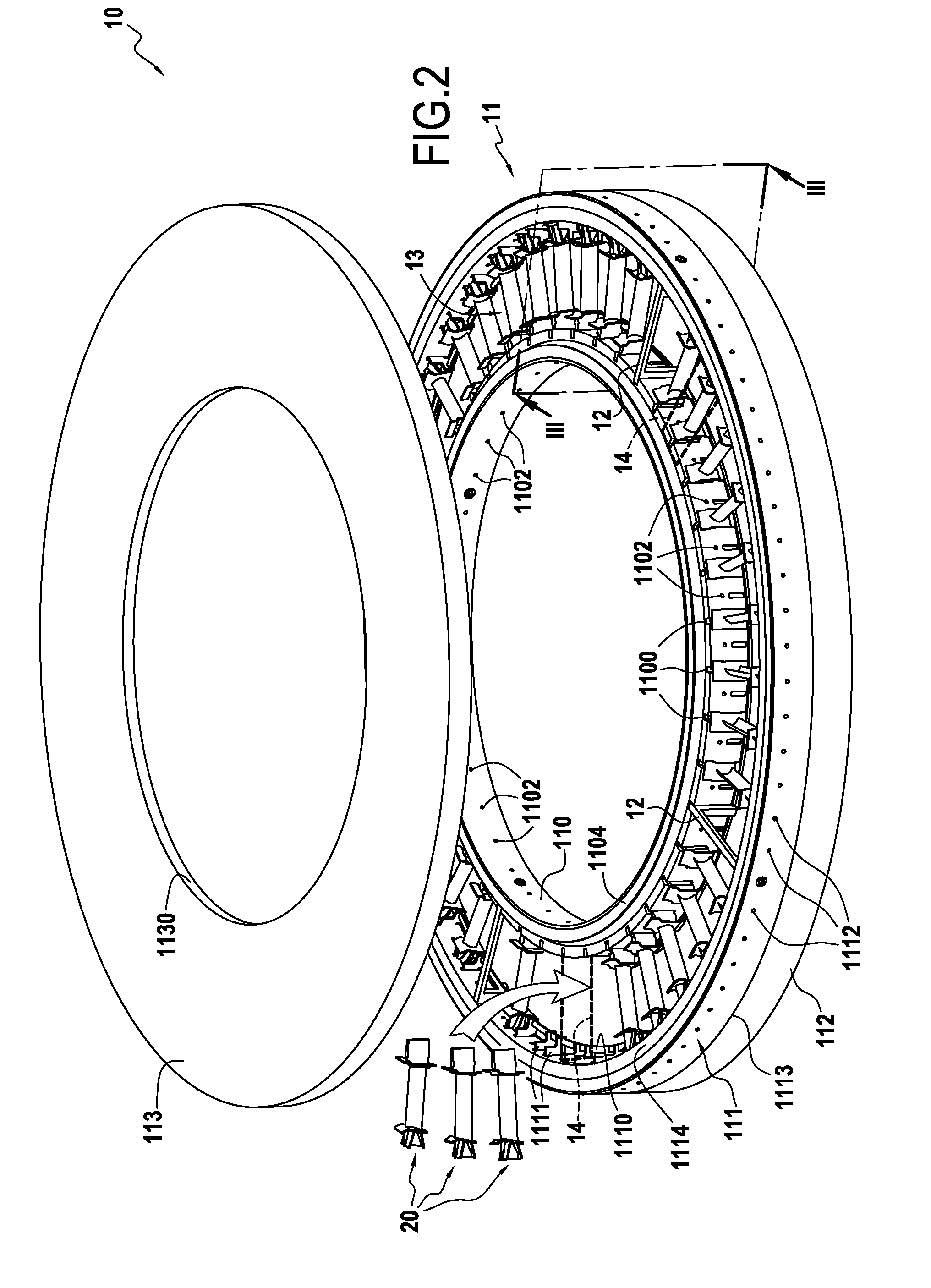
[0040]FIGS. 1 to 3 show a loader device or tooling 10 that, once loaded with substrates for densifying, is to be inserted in a reaction chamber in an industrial installation for chemical vapor infiltration. In the presently-described example, the tooling 10 is designed to receive fiber preforms 20 for aeroengine blades.

[0041]Each preform 20 extends in a longitudinal direction between two ends 21 and 22 and comprises an airfoil 120 and a root 130 formed by a portion of greater thickness, e.g. having a bulb-shaped section that is extended by a tang 132 (FIG. 3). The airfoil 120 extends in a longitudinal direction between its root 130 and its tip 121 and in cross-section it presents a curved profile of varying thickness defining two faces 122 and 123 that correspond respectively to the suction side and to the pressure side of the airfoil 120. In the presently-described example, the airfoil 120 also has an inner platform 140 for the blade and an outer platform 160 for the blade.

[0042]Th...


PUM

PropertyMeasurementUnit
three-dimensional shapesaaaaaaaaaa
radial dimensionsaaaaaaaaaa
shapeaaaaaaaaaa

Abstract

A loader device for loading porous substrates of three-dimensional shapes extending mainly in a longitudinal direction into a reaction chamber of an infiltration oven for densification of the preforms by directed flow chemical vapor infiltration. The device comprising at least one annular loader stage formed by first and second annular vertical walls arranged coaxially relative to each other and defining between them an annular loader space for the porous substrates to be densified. First and second plates respectively cover the bottom portion and the top portion of the annular loader space. The first and second annular vertical walls include support elements arranged in the annular loader space so as to define between them unit loader cells, each for receiving a respective substrate to be densified. The device also comprises gas feed orifices and gas exhaust orifices in the vicinity of each unit loader cell.

Description

BACKGROUND OF THE INVENTION[0001]The present invention relates to the techniques of chemical vapor infiltration that are used in particular when making parts out of thermostructural composite material. The invention relates more particularly to densifying porous substrates of complex three-dimensional shape such as fiber preforms for use in fabricating aeroengine blades, the substrates being densified by depositing a matrix therein.[0002]In order to fabricate parts out of composite material, and in particular parts made of thermostructural composite material constituted by a refractory fiber preform (using carbon or ceramic fibers, for example) that is densified by a refractory matrix (e.g. made of carbon and / or ceramic), it is common practice to use chemical vapor infiltration methods. Examples of such parts are thruster nozzles made of carbon-carbon (C—C) composite, brake disks, in particular for airplane brakes, made of C—C composites, or blades made of ceramic matrix composites ...

Claims


Application Information

Patent Timeline
Patent Type & Authority Applications(United States)
IPC IPC(8): C23C16/04C23C16/455
CPCC23C16/455C23C16/045C23C16/458
Inventor BERTRAND, SEBASTIENLAMOUROUX, FRANCKGOUJARD, STEPHANE
Owner SAFRAN CERAMICS SA
Why Eureka
Try Eureka