Method for manufacturing a container containing a content fluid, a method for placing an inside of a container under a positive pressure, a filled container, a blow molding method, and a blow molding device

a technology of content fluid and manufacturing method, which is applied in the direction of liquid handling, bundling machine details, applications, etc., can solve the problems of deformation or breakage of containers, and achieve the effect of preventing leakage of content fluid, pressure in the inside of the container, and ensuring product quality

Active Publication Date: 2015-03-19
DISCMA
View PDF1 Cites 40 Cited by
  • Summary
  • Abstract
  • Description
  • Claims
  • Application Information

AI Technical Summary

Benefits of technology

[0060]According to the method for manufacturing a container containing a content fluid of the present invention, shrinkage and deformation of a bottle over a passage of time after the sealing step are prevented.
[0061]According to the method for placing an inside of a container under a positive pressure of the present invention, since the method utilizes a blow molding method using a content fluid to be filled in the container as the pressure medium, the content fluid may be filled at the time of molding of the container. Furthermore, by sealing a mouth portion of the container in a state where the content fluid is filled after the molding, in particular, immediately after the molding, the inside of the container is placed under the positive pressure due to reduction in volume of the container resulting from after-shrinkage of a circumferential wall of the container after the molding subsequent to the sealing, without using an additional measure such as adding a drip of liquid nitrogen and without compromising productivity compared with a conventional blow molding method using a liquid as the pressure medium.
[0062]According to the blow molding device and the blow molding method using the blow molding device according to the present invention, a predetermined volume of head space is formed in a container obtained by blowing a preform in a metal mold with use of a content fluid. As a result, until the step of capping a mouth portion of the container after blow molding, leakage of the content fluid is favorably prevented. Furthermore, since a bottom portion of the container has a shape bulging toward the outside of the container, when pressure in the inside of the container is decreased after the capping, the shape of the bottom portion is restored. As a result, irregular deformation due to the decreased pressure is favorably prevented.

Problems solved by technology

When an inside of the filled container is particularly in a reduced pressure state, buckling strength is deteriorated, possibly resulting in deformation or breakage of the container under load applied during transportation.

Method used


Image

  • Method for manufacturing a container containing a content fluid, a method for placing an inside of a container under a positive pressure, a filled container, a blow molding method, and a blow molding device
  • Method for manufacturing a container containing a content fluid, a method for placing an inside of a container under a positive pressure, a filled container, a blow molding method, and a blow molding device
  • Method for manufacturing a container containing a content fluid, a method for placing an inside of a container under a positive pressure, a filled container, a blow molding method, and a blow molding device

Examples


first embodiment

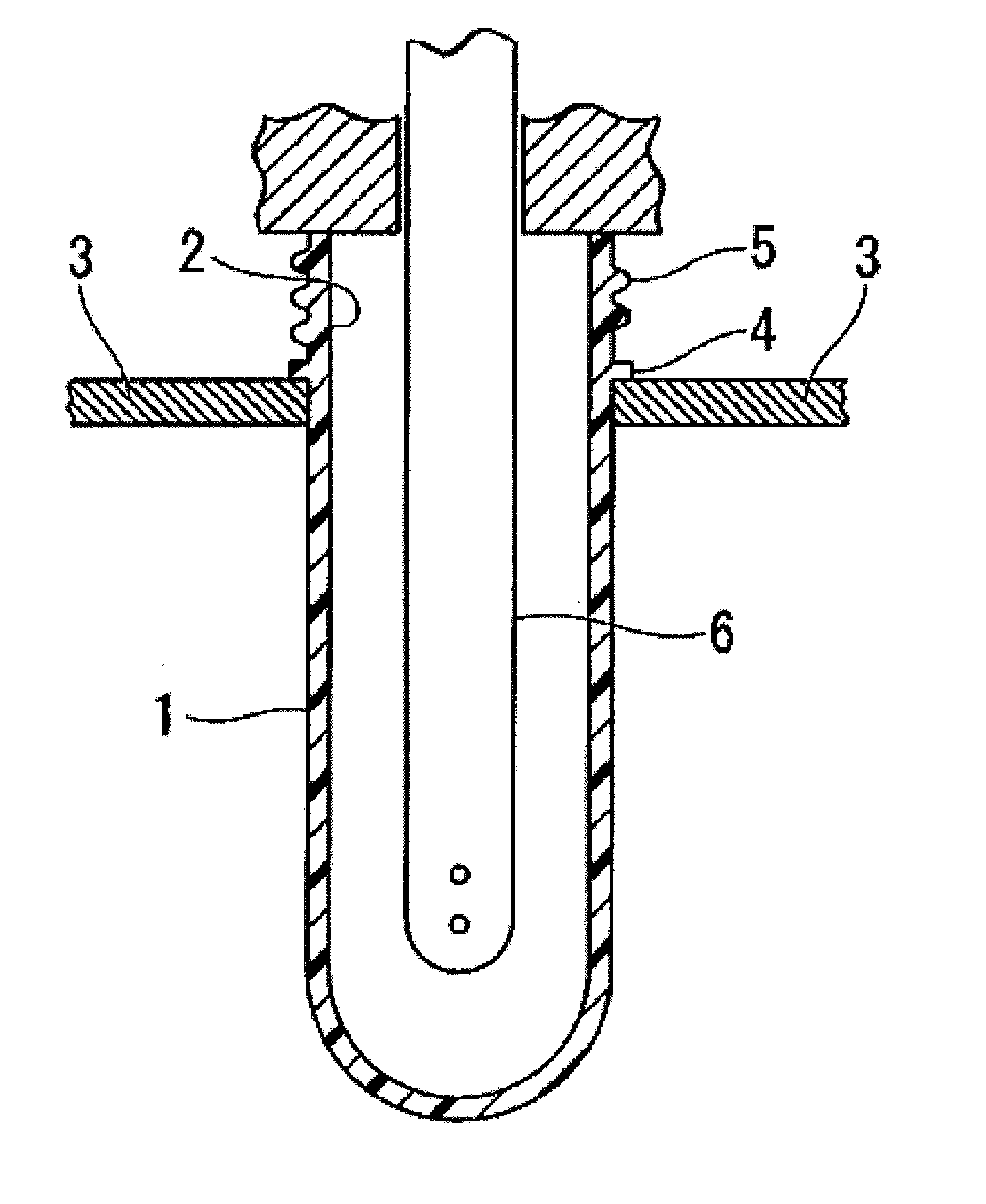
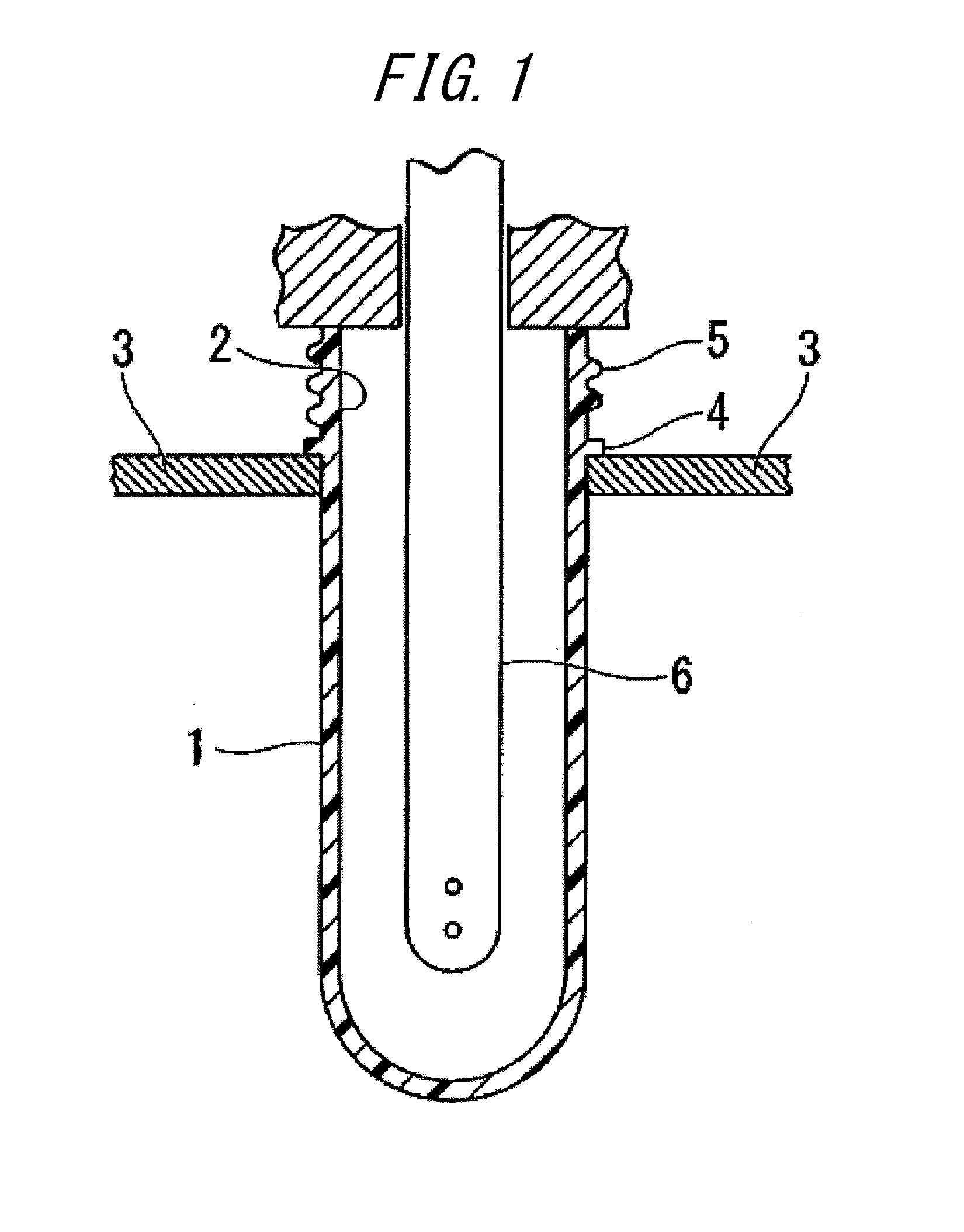
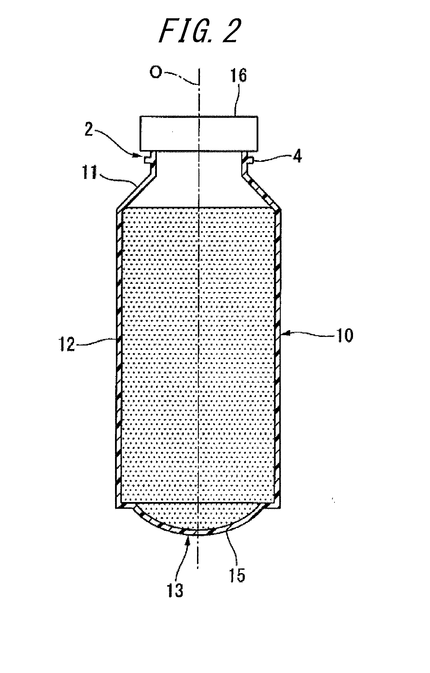
[0090]A method for manufacturing a container (which may also be referred to below as a bottle) containing a content fluid according to A first embodiment of the present invention is described below with reference to FIGS. 1-4.

[0091]In the method for manufacturing a bottle containing a content fluid according to the present embodiment, the molding step and the sealing step are performed. In the molding step, a bottomed tubular preform that is heated to a temperature at which the preform is stretchable is stretched so as to form the bottle by means of pressure of the content fluid injected into the preform through a mouth portion of the preform. In the sealing step, the content fluid is sealed by fitting a cap body to the mouth portion. In the molding step, an invertible deforming portion is also formed in the bottle. The invertible deforming portion is freely invertible and deformable toward an inside of the bottle. After the sealing step before a temperature of the bottle decreases ...

second embodiment

[0112]Next, with reference to FIGS. 5-9, a description is given of a method for placing an inside of a container under a positive pressure according to a second embodiment.

[0113]FIG. 5 is a front view illustrating one example of a blow molded container in the method for placing the inside of the container under the positive pressure according to the present embodiment.

[0114]The container 141 includes a mouth portion 142, a body portion 144 that is connected to a lower end of the mouth portion 142 and that extends downward, and a bottom portion 145 that closes a lower end opening of the body portion 144. The container 141 is made of a propylene-ethylene random copolymer resin (J246M manufactured by Prime Polymer Co., Ltd.), which is a PP-based resin, and is a bottle having a diameter of 73.5 mm, a nominal volume of 360 ml, and weight of 5 g.

[0115]FIG. 6 is a schematic view illustrating a blow molding device used for the method for placing the inside of the container under the positiv...

example 1

[0137]The temperature of the liquid L 20° C., the temperature of the metal mold 20° C.


PUM

PropertyMeasurementUnit
weightaaaaaaaaaa
volumeaaaaaaaaaa
diameteraaaaaaaaaa

Abstract

Provided is a method for manufacturing a container containing a content fluid, including: a molding step of stretching a bottomed tubular preform that is heated to a temperature at which the preform is stretchable so as to form the container by means of pressure of the content fluid injected into the preform through a mouth portion; a sealing step of sealing the content fluid by fitting a cap body to the mouth portion; and a pressurizing step of increasing an inner pressure of the container, wherein the container includes an invertible deforming portion that is freely invertible and deformable toward an inside of the container, and in the pressurizing step, the inner pressure of the container is increased by reducing a volume of the container by inverting and deforming the invertible deforming portion toward the inside of the container.

Description

TECHNICAL FIELD[0001]The present invention relates to a method for manufacturing a container containing a content fluid.[0002]The present invention also relates to a method for placing an inside of the container under a positive pressure, and a filled container that contains a fluid therein and that is under a positive pressure state.[0003]The present invention also relates to a blow molding device for a preform, and a blow molding method for a preform.[0004]This application claims priority to and the benefit of Japanese Patent Application No. 2012-079005 filed on Mar. 30, 2012, Japanese Patent Application No. 2012-145408 filed on Jun. 28, 2012, Japanese Patent Application No. 2012-170180 filed on Jul. 31, 2012, the contents of which are incorporated herein by reference.BACKGROUND ART[0005]As has been conventionally known, there is a method for manufacturing a bottle containing a content fluid, including: the molding step of biaxially stretching a preform in a heated state by inject...

Claims


Application Information

Patent Timeline
Patent Type & Authority Applications(United States)
IPC IPC(8): B65B61/24B67C3/22B65B47/08
CPCB65B61/24B67C2003/227B67C3/22B65B47/08B29C49/06B29C49/541B65D1/0261B65D1/0276B67C3/045B67C7/00B29C49/783B29C49/12B29C2049/4664B29C2049/4892B29C49/58B29K2023/12B29K2067/003B29C49/4273B29C49/78B29C2049/023B29C49/42802B29C49/4283B29C2949/0715
Inventor SATO, SUMITOTAMURA, NOBUYUKINAGASHIMA, TAKESHIOKUYAMA, YUICHISHIMIZU, KAZUHIKOTANAKA, TOSHIMASA
Owner DISCMA
Why Eureka
Try Eureka