Power converters for wide input or output voltage range and control methods thereof

a power converter and input or output voltage technology, applied in the direction of electric variable regulation, process and machine control, instruments, etc., can solve the problems of increased switching losses of converters, inconvenient use of resonant converters, and inability to meet the needs of wide output voltage range applications. achieve the effect of improving efficiency of power converters

Active Publication Date: 2015-03-19
DELTA ELECTRONICS INC
View PDF15 Cites 28 Cited by
  • Summary
  • Abstract
  • Description
  • Claims
  • Application Information

AI Technical Summary

Benefits of technology

[0008]According to one embodiment of the present invention, a method improves efficiency in power converters operating with a wide input or output voltage range by topology morphing (i.e., changing the power converter's topology). Generally, in a method of the present invention, the power converter topology is adapted to that which is optimized for a given input or output voltage condition. The topology adapts to a control signal that is responsive to input or output operating conditions, or to an external control signal.

Problems solved by technology

The detrimental effect of a wide input or output voltage range on conversion efficiency is more severe in resonant converters than in pulse-width-modulated (PWM) converters.
As a result, these converters suffer from increased switching losses when they operate away from the minimum input voltage or the maximum output voltage.
Therefore, resonant converters—including the most efficient series-resonant LLC converter topology—are not suitable for applications with a wide output voltage range.
Thus, any efficiency drop associated with an output voltage decrease for such converters is primarily due to other factors (e.g., an increased conduction loss resulting from a reduced duty cycle, which increases the RMS current).
While this approach has been demonstrated to improve efficiency, as compared to a single-stage conversion, it is not preferred as the increased number of components increases circuit complexity and cost.

Method used


Image

  • Power converters for wide input or output voltage range and control methods thereof
  • Power converters for wide input or output voltage range and control methods thereof
  • Power converters for wide input or output voltage range and control methods thereof

Examples


Embodiment Construction

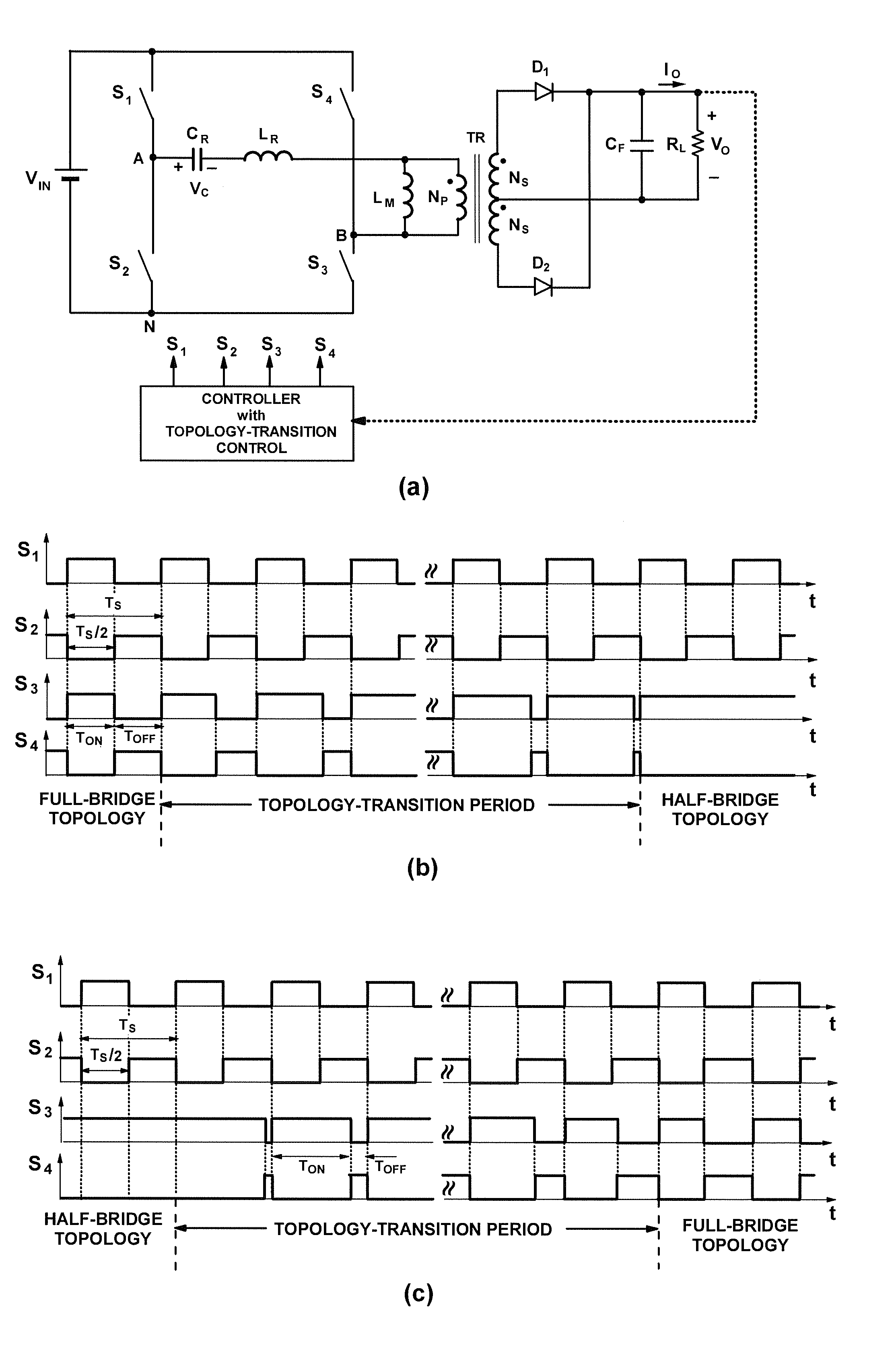
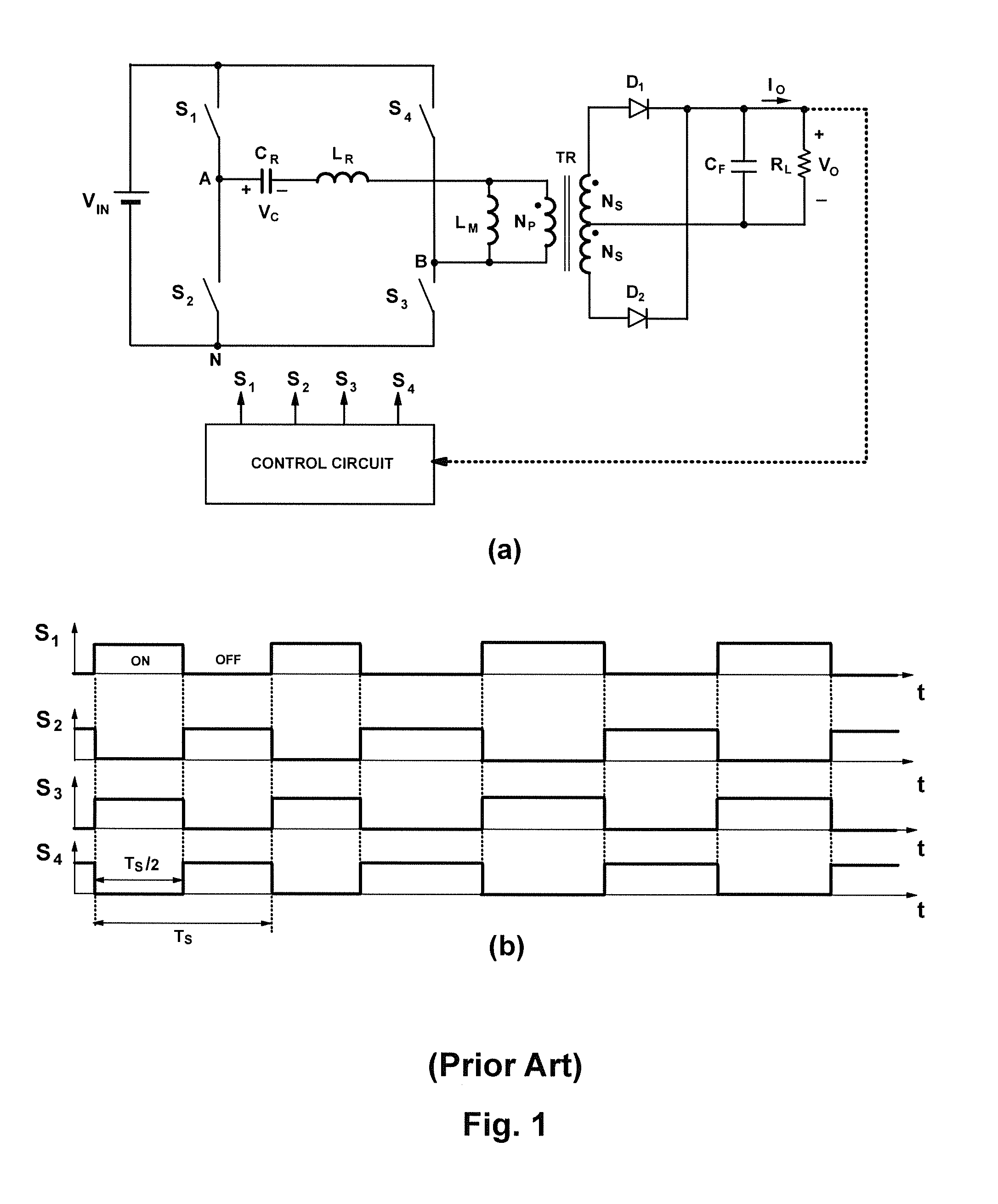
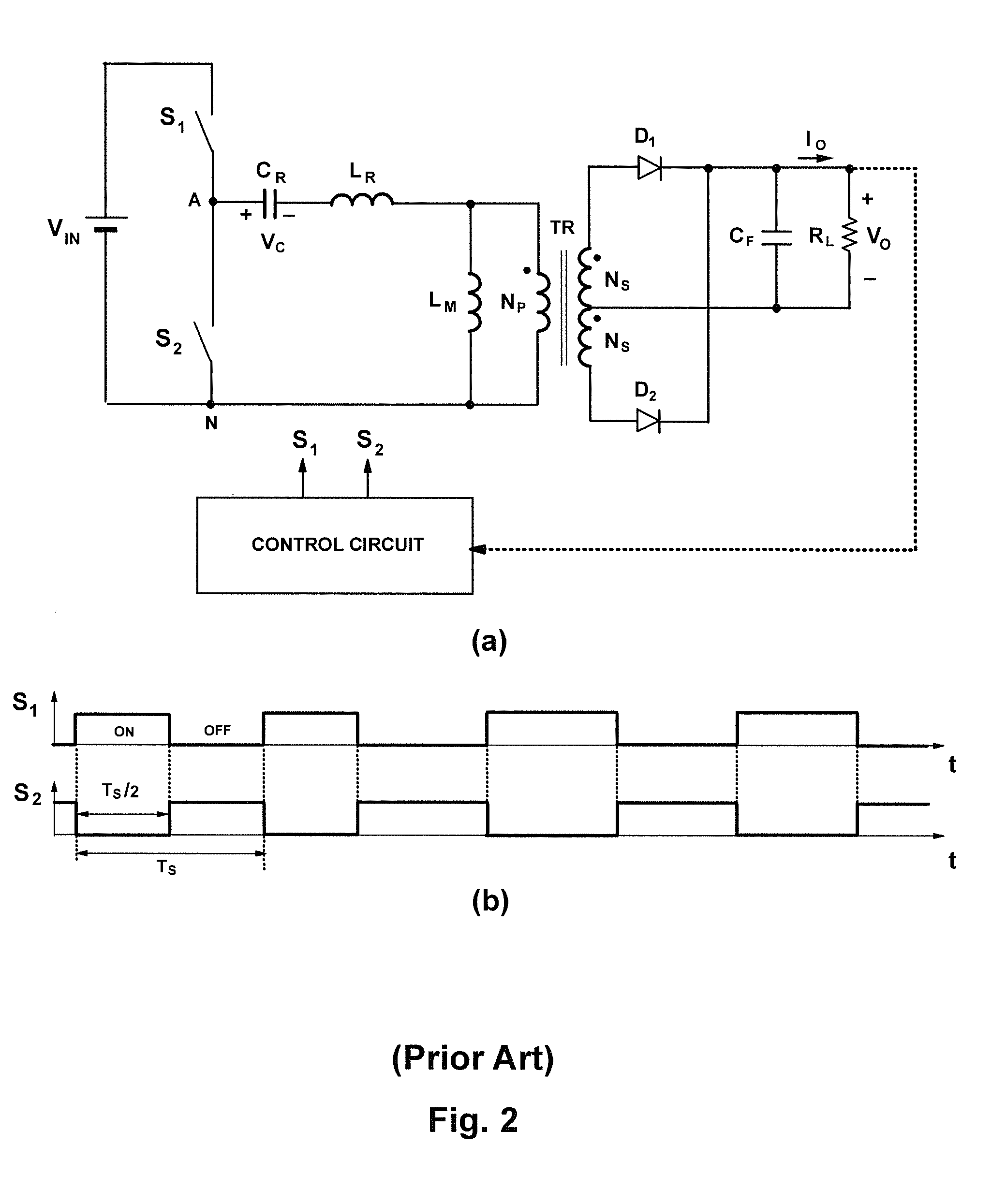
[0018]FIGS. 1(a) and 2(a) show simplified circuits or models of conventional full-bridge (FB) and half-bridge (HB) LLC resonant converters, respectively. FIGS. 1(b) and 2(b) are the corresponding timing diagrams for the principal switches of the FB and HB LLC resonant converters, respectively. Both the circuits of FIGS. 1(a) and 2(a) use conventional variable switching-frequency control to regulate the output voltage. In the FB LLC converter shown in FIG. 1(a), control is achieved by simultaneously switching the S1 and S3 switch pair and S2 and S4 switch pair in a complementary fashion, with each switch operating at a 50% duty ratio, as illustrated in FIG. 1(b). Similarly, in the HB LLC converter of FIG. 2(a), the variable switching-frequency control is achieved by switching switches S1 and S2 in a complementary fashion, with each switch operating at a 50% duty ratio, as illustrated in FIG. 2(b). The switching frequency for each LLC converter is a function of input voltage VIN, outp...


PUM


Abstract

A power converter topology is adapted for efficiency according to input voltage, output voltage or output current conditions. Topology adaptation is achieved by control responsive to the input and output operating conditions, or to one or more external control signals. Transition between any two topologies is implemented by pulse width modulation in the two switches in one of two bridge legs of a full bridge converter. When transitioning from full-bridge to half-bridge topology, the duty ratio of one switch in one leg of the full bridge is increased, while simultaneously the duty ratio of the other switch in the same leg is reduced until one switch is continuously on, while the other switch is continuously off. The transition from the half-bridge to the full-bridge topology is accomplished by modulating the same switches such that, at the end of the transition, both switches operate with substantially the same duty cycle.

Description

BACKGROUND OF THE INVENTION[0001]1. Field of the Invention[0002]The present invention relates to power converters that can efficiently operate with a wide input-voltage or output-voltage range.[0003]2. Description of the Related Art[0004]In many applications, power conversion circuits are required to operate with a wide input or output voltage range. For example, most single-phase AC / DC power supplies in today's computer and telecommunication (“telecom”) power systems must operate in the universal AC line range between 90 VRMS and 264 VRMS and must provide a regulated output voltage. Typically, telecom AC / DC power supplies provide a regulated output voltage between 42 V to 58 V, while power supplies for desktop, networking, and server applications provide a single constant output voltage or multiple constant output voltages. However, to further improve energy efficiency, an emerging requirement in server power supplies is a single output voltage selectable from two predetermined lev...

Claims


Application Information

Patent Timeline
Patent Type & Authority Applications(United States)
IPC IPC(8): H02M3/335H02M1/00
CPCH02M3/33507H02M1/10Y02B70/10H02M1/0058H02M3/33573H02M3/01
Inventor JOVANOVIC, MILAN M.IRVING, BRIAN T.
Owner DELTA ELECTRONICS INC
Why Eureka
Try Eureka