Filter enhancer and method

a filter enhancer and filter technology, applied in the field of radio frequency (rf) isolation filters, can solve the problems of manual tuning, high cost, bulky, etc., and achieve the effects of reducing duplexer cost, reducing duplexer insertion loss, and reducing size and weigh

Inactive Publication Date: 2015-03-19
SCINTERA NETWORKS
View PDF17 Cites 37 Cited by
  • Summary
  • Abstract
  • Description
  • Claims
  • Application Information

AI Technical Summary

Benefits of technology

[0012]According to one embodiment of the present invention, a rusty bolt effect is canceled by using a polynomial function circuit coupled to the input terminal of the passive filter for generating cancellation signals to passive intermodulation products, a filter for filtering the cancellation signals, and a summer for combining the filtered ...

Problems solved by technology

Passive duplexer 101 has the disadvantages of being both costly and bulky, and requi...

Method used


Image

  • Filter enhancer and method
  • Filter enhancer and method
  • Filter enhancer and method

Examples


Embodiment Construction

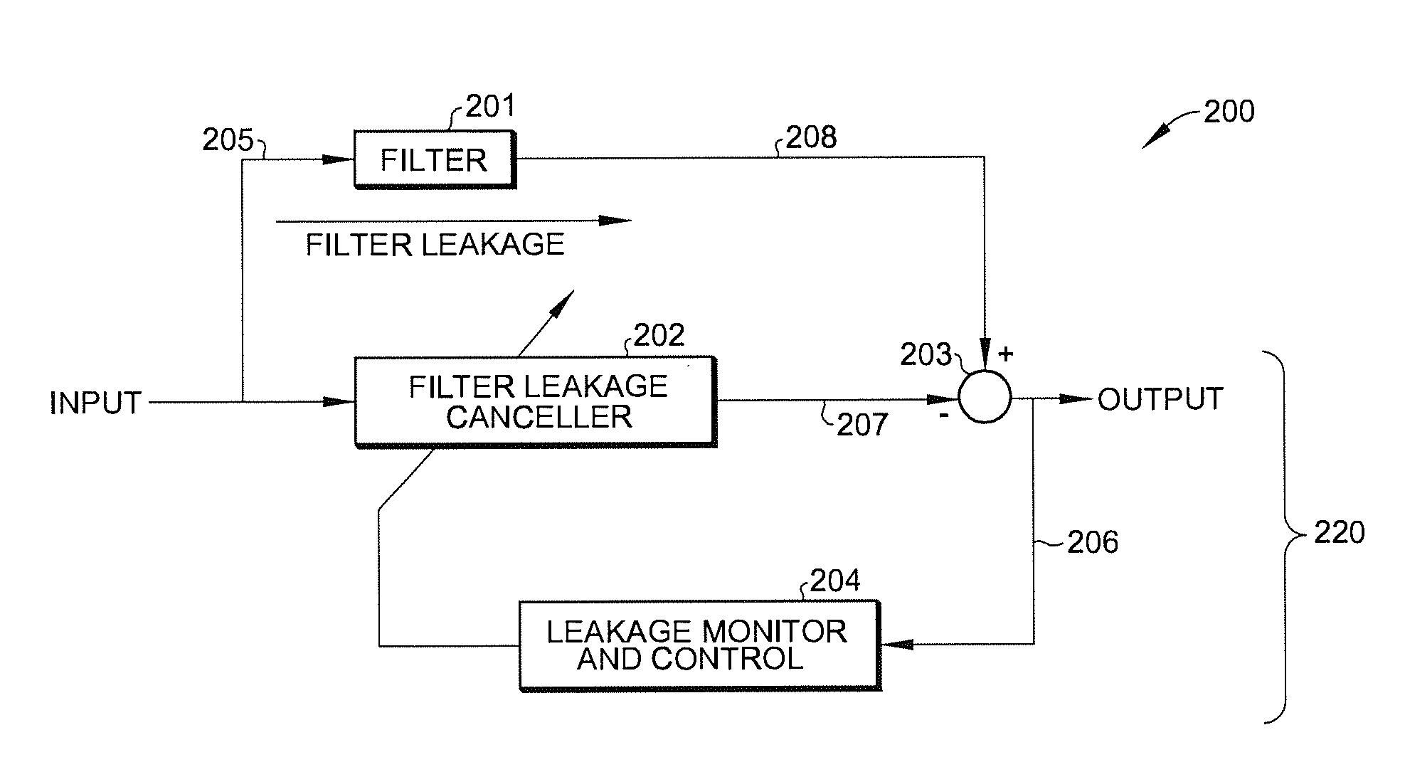
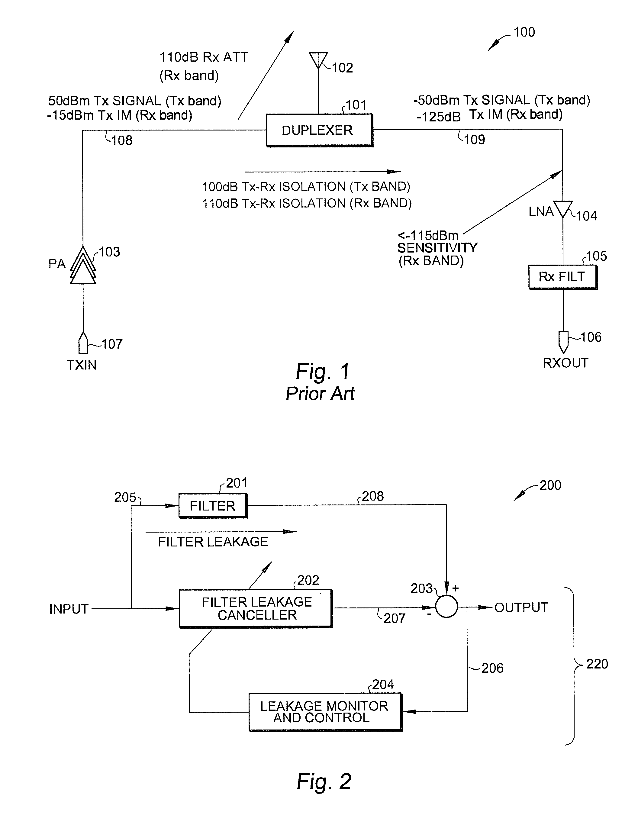
[0036]The present invention provides a filter enhancer for improving performance of a duplexer circuit (e.g., duplexer 101 of FIG. 1). FIG. 2 is a block diagram of filter enhanced circuit 200, in accordance with one embodiment of the present invention. As shown in FIG. 2, filter enhanced circuit 200 includes filter 201, which receives an input signal at terminal 205 and a filtered signal at terminal 208. In this detailed description, filter 201 is exemplified by a passive duplexer circuit in an RF application that includes an input terminal for receiving from a transmitter an RF signal to be transmitted, a bidirectional antenna terminal which serves both transmission and reception, and an output terminal for providing an RF signal to a receiver. The RF signal to be provided to the receiver is picked up by the antenna coupled to the antenna terminal. To enhance isolation between the transmitter and the receiver across filter 201, leakage in filter 201 is canceled by leakage canceller...


PUM


Abstract

A filter enhancer provides greater performance in a passive filter. The passive filter has an input terminal for receiving a signal in a first frequency band and an output terminal for providing a signal in a second frequency band. The filter enhancer includes: (a) a first canceller circuit coupled between input terminal and output terminal, the first canceller circuit including a first finite impulse response (FIR) filter for attenuating signals in the first frequency band; and (b) a control circuit coupled to output terminal and first canceller circuit for providing adaptive coefficients for configuring the first FIR filter. The first FIR filter may be implemented by either a digital FIR filter or an analog FIR filter. The filter enhancer may further include a second canceller circuit coupled between input terminal and output terminal, the second canceller circuit including a second FIR filter for attenuating signals in the second frequency band.

Description

BACKGROUND OF THE INVENTION[0001]1. Field of the Invention[0002]The present invention relates generally to radio frequency (RF) isolation filters. In particular, the present invention relates to RF isolation filters used in passive components used in conjunction with RF transceivers, such as duplexers, diplexers or other filters types.[0003]2. Discussion of the Related Art FIG. 1 shows transceiver duplexer circuit 100 in an RF application. As shown in[0004]FIG. 1, transceiver circuit 100 receives an RF signal at transmitter input terminal 107. The RF signal is amplified by RF power amplifier 103 for transmission. In one typical application, RF power amplifier 103 provides +50 dBm signal power in the transmitter frequency band and unwanted intermodulation (IM) products or noise of −15 dBm in the receiver frequency band. The amplified RF signal is received into input terminal 108 of duplexer 101, where the signal is provided to antenna 102 for transmission. Antenna 102 serves both the...

Claims


Application Information

Patent Timeline
IPC IPC(8): H04B3/23
CPCH04B3/23H04B1/525
Inventor CHARLON, OLIVIERYU, QIAN
Owner SCINTERA NETWORKS
Why Eureka
Try Eureka