
Turbocharger

a technology of turbocharger and cylinder head, which is applied in the direction of liquid fuel engines, sliding contact bearings, machines/engines, etc., can solve the problems of hindering the flow of lubricant, damage to bearings or occlusion of grooves, etc., to improve the performance of bearings, reduce bearing damage, and improve lubrication performance

Active Publication Date: 2015-03-19
IHI CORP
View PDF3 Cites 9 Cited by
  • Summary
  • Abstract
  • Description
  • Claims
  • Application Information

AI Technical Summary

Benefits of technology

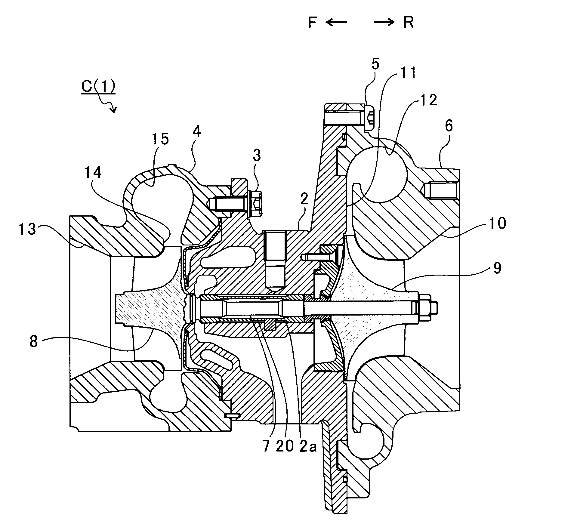
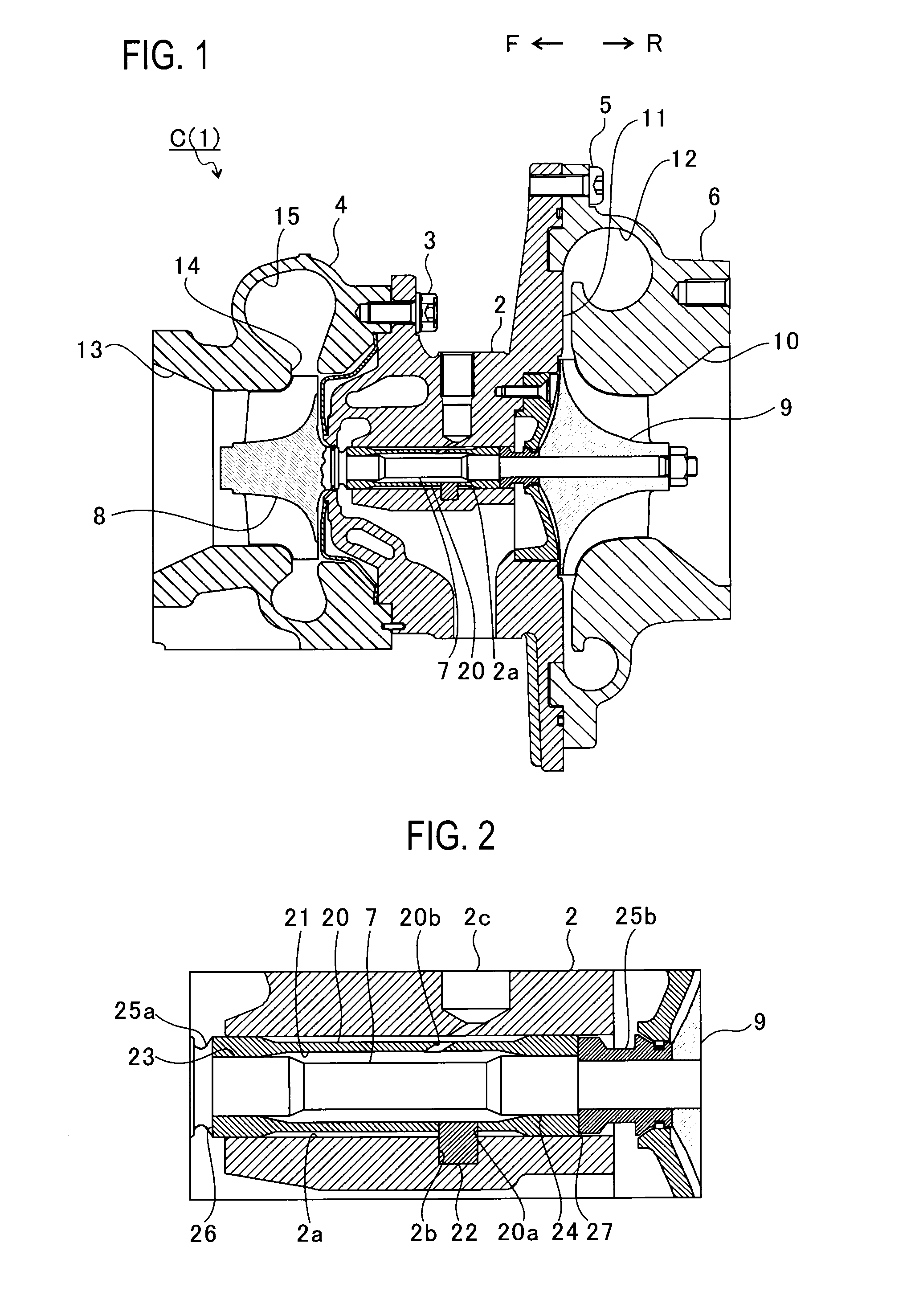
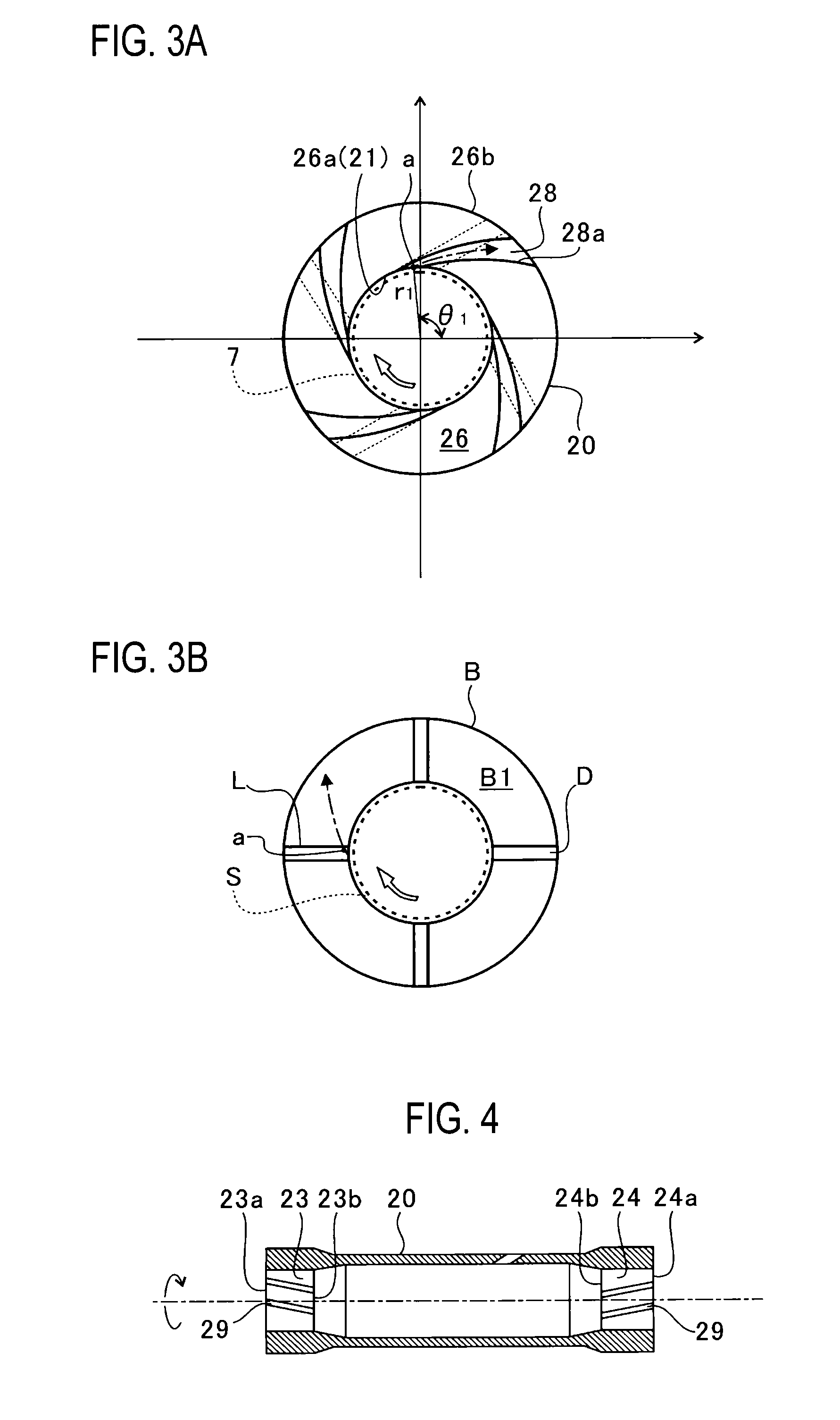
The patent aims to improve the performance of a bearing in a turbocharger to prevent damage and ensure good lubrication. It does this by improving the bearing's ability to discharge foreign substances that may enter the lubricant. This helps to reduce damage to the bearings and improve overall lubrication performance.

Problems solved by technology

As a result, in the turbocharger described in PTL1, the foreign substance may run off the grooves in a circumferential direction and get caught between the thrust collar and the bearing, thereby damaging the bearing or occluding the grooves to hinder the lubricant from flowing in the grooves.

Method used


Image

  • Turbocharger
  • Turbocharger
  • Turbocharger

Examples


modified examples

[0059]FIG. 5 is a schematic cross-sectional view of the inside of a bearing housing 2 of a modified example of the embodiment. As shown in FIG. 5, in addition to the semi-floating metal (the bearing 20), thrust bearings 30, 32 and a thrust collar 34 are arranged in the modified example. As shown in FIG. 5, the thrust collar 34 is disposed on a compressor impeller 9-side portion of the turbine shaft 7. The thrust bearings 30, 32 are disposed, respectively, on one axial-direction side (the left side of the thrust collar 34 in FIG. 5) and an opposite axial-direction side (the right side of the thrust collar 34 in FIG. 5) of the thrust collar 34 (the opposing portion).

[0060]The thrust collar 34 is fixed to the turbine shaft 7, and rotates integrally with the turbine shaft 7. The thrust collar 34 includes: an opposing surface 34b which faces the thrust bearing 30; and an opposing surface 34a which faces the thrust bearing 32.

[0061]The thrust bearing 30 includes: a through-hole 30a which ...


PUM


Abstract

A turbocharger includes: a bearing provided in a turbocharger body, and configured to rotatably support a turbine shaft in an insertion hole formed in the bearing; and an opposing portion which faces an end surface of the bearing in an axial direction of the turbine shaft. An end-surface guide portion is provided to any one of an opposing surface of the bearing which faces the opposing portion, and an opposing surface of the opposing portion which faces the bearing. The end-surface guide portion configured to make the insertion hole and an outer peripheral edge of the end surface of the bearing in radial directions of the turbine shaft communicate with each other extends forward in a rotational direction of the turbine shaft from a part of the end surface of the bearing which communicates with the insertion hole.

Description

CROSS REFERENCE TO RELATED APPLICATIONS[0001]This application is a continuation application of International Application No. PCT / JP2013 / 067514, filed on Jun. 26, 2013, which claims priority to Japanese Patent Application No. 2012-146253, filed on Jun. 29, 2012, the entire contents of which are incorporated by references herein.BACKGROUND OF THE INVENTION[0002]1. Field of the Invention[0003]The present invention relates to a turbocharger including a bearing configured to receive thrust load.[0004]2. Description of the Related Art[0005]Turbochargers have been conventionally known in which a turbine shaft is rotatably supported by a bearing housing with a turbine impeller provided to one end of the turbine shaft, and with a compressor impeller provided to the other end of the turbine shaft. This turbocharger is connected to an engine. The turbine impeller is rotated by an exhaust gas discharged from the engine. The rotation of the turbine impeller is transmitted to the compressor impel...

Claims


Application Information

Patent Timeline
Patent Type & Authority Applications(United States)
IPC IPC(8): F04D29/051
CPCF04D29/051F02B39/14F16C2360/24F04D25/024F04D29/0513F04D29/057F04D29/063F05D2250/15F01D25/166F01D25/18F05D2220/40F05D2240/52F05D2240/54F05D2260/607F05D2240/53F16C27/02F16C17/10F16C33/1065F16C17/107F16C33/107
Inventor UNEURA, YUTAKAOTANI, TOMOMIDAITO, YUICHI
Owner IHI CORP
Learn More