Line balancing ups

a technology of line balancing and ups, applied in the field of power management, can solve the problems of increased reliability and efficiency costs, increased power consumption, and inefficient electric utility service, and achieve the effects of reducing load, reducing load, and reducing load

Active Publication Date: 2015-03-26
SCHNEIDER ELECTRIC IT CORP
View PDF2 Cites 10 Cited by
  • Summary
  • Abstract
  • Description
  • Claims
  • Application Information

AI Technical Summary

Problems solved by technology

Since the DC bus is always powered either by mains or the battery, the output power of the UPS is uninterrupted if the mains fails and the battery is sufficiently charged.
While uninterruptible power supplies are typically used to provide a continuous source of power at a local level (e.g., at a data center or in an office or home), such devices primarily depend on utility power due to the limited capacity of the batteries or other energy storage devices used in conjunction with the UPS.
Historically, electric utility service has been demand-driven and inefficient, but increasingly technology is being employed to improve the availability, reliability and efficiency of the electric grid.
Furthermore, there may be times when the load increases substantially above the baseload capacity of the power utility with little or no warning, which introduces additional reliability and efficiency costs.
Today many power distributors attempt to match the power generated with the power consumed by stepping up or stepping down individual phases in the power distribution transformers (away from the power consumers); however, this only helps in outbalancing any unbalance in the line voltage and does not balance the grid load nor help reduce the unwanted losses in the distribution lines caused by the unbalance in the grid current.
Therefore, it can be difficult to accomplish the power management objectives of the smart grid without some degree of cooperation between the electric utility and power consumers.

Method used


Image

  • Line balancing ups
  • Line balancing ups
  • Line balancing ups

Examples


Embodiment Construction

[0029]Embodiments of this invention are not limited in their application to the details of construction and the arrangement of components set forth in the following description or illustrated in the drawings. Embodiments of the invention are capable of other embodiments and of being practiced or of being carried out in various ways. Also, the phraseology and terminology used herein is for the purpose of description and should not be regarded as limiting. The use of “including,”“comprising,” or “having,”“containing,”“involving,” and variations thereof herein, is meant to encompass the items listed thereafter and equivalents thereof as well as additional items.

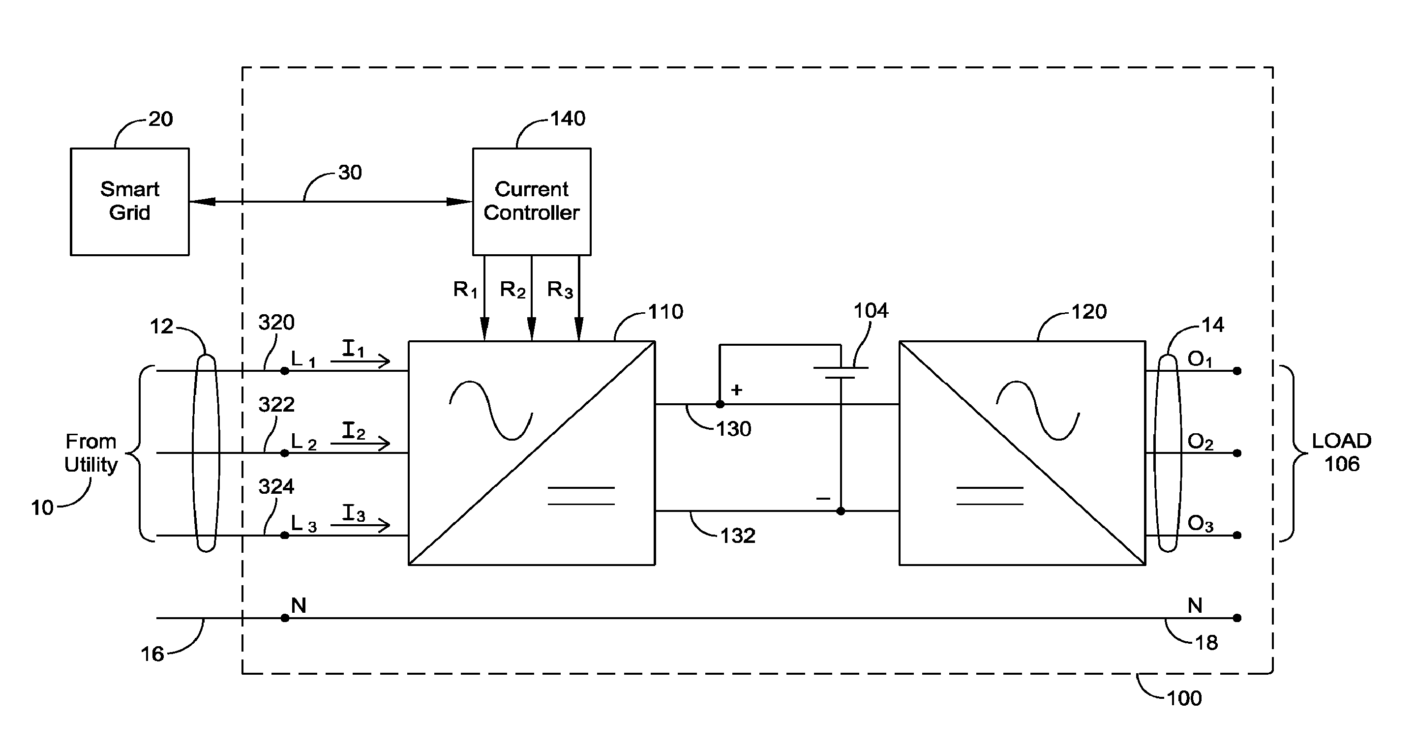
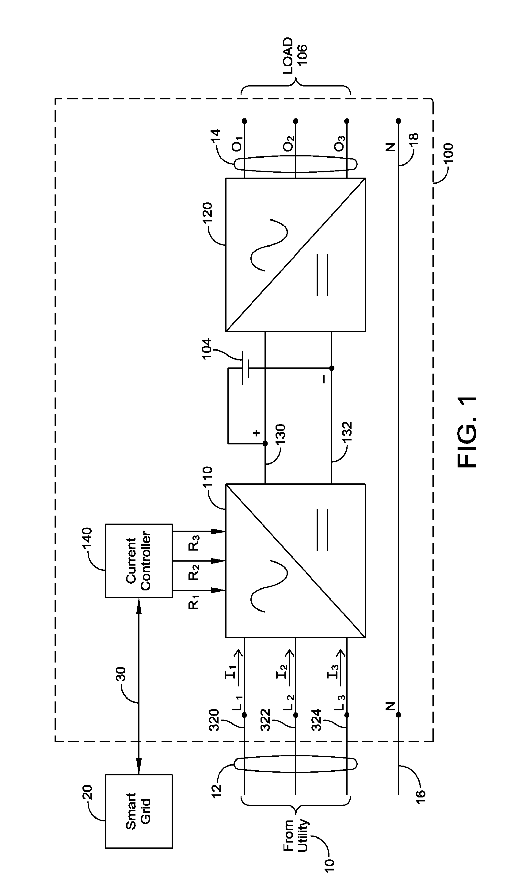
[0030]Various embodiments relate to power conversion in a UPS, including polyphase power distribution to a load (e.g., three phase power). As used herein, the term “polyphase” means two or more phases. Although the use of three-phase power is common, it should be appreciated that, in some embodiments, the UPS may be a two-phase,...


PUM


Abstract

A method for controlling an uninterruptible power supply (UPS) having a polyphase power input and an input power circuit coupled to the polyphase power input includes determining to reduce a load on a first phase of the polyphase power input, and in response thereto, controlling the input power circuit to reduce a first input current drawn from the first phase by a first amount and increase a second input current drawn from a second phase of the polyphase power input by a second amount. The UPS may determine to reduce the load on the first phase in response to a request from a smart grid to reduce the load on the first phase or in response to a local determination to reduce the load on the first phase.

Description

BACKGROUND OF THE INVENTION[0001]1. Field of Invention[0002]Embodiments of the invention relate generally to power management, and more particularly, to dynamic load adjustment per phase of a polyphase uninterruptible power supply.[0003]2. Discussion of Related Art[0004]An uninterruptible power supply (UPS) is used to provide backup power to an electrical device, or load, while the primary power source, or mains, is unavailable. A conventional UPS rectifies input power provided by an electric utility using a power factor correction circuit (PFC) to provide a DC voltage to a DC bus. The rectified DC voltage is typically used to charge a battery while mains power is available, as well as to provide power to the DC bus. In the absence of mains power, the battery provides power to the DC bus. From the DC bus, an inverter generates an AC output voltage to the load. Since the DC bus is always powered either by mains or the battery, the output power of the UPS is uninterrupted if the mains...

Claims


Application Information

Patent Timeline
Patent Type & Authority Applications(United States)
IPC IPC(8): H02J9/06H02J3/26
CPCH02J3/26H02J9/06H02J9/062Y02E40/50
Inventor GAMBORG, GORM
Owner SCHNEIDER ELECTRIC IT CORP
Why Eureka
Try Eureka