

Charging and discharging control circuit and battery device
- Summary
- Abstract
- Description
- Claims
- Application Information
AI Technical Summary
Benefits of technology
Problems solved by technology
Method used
Image


Examples
first embodiment
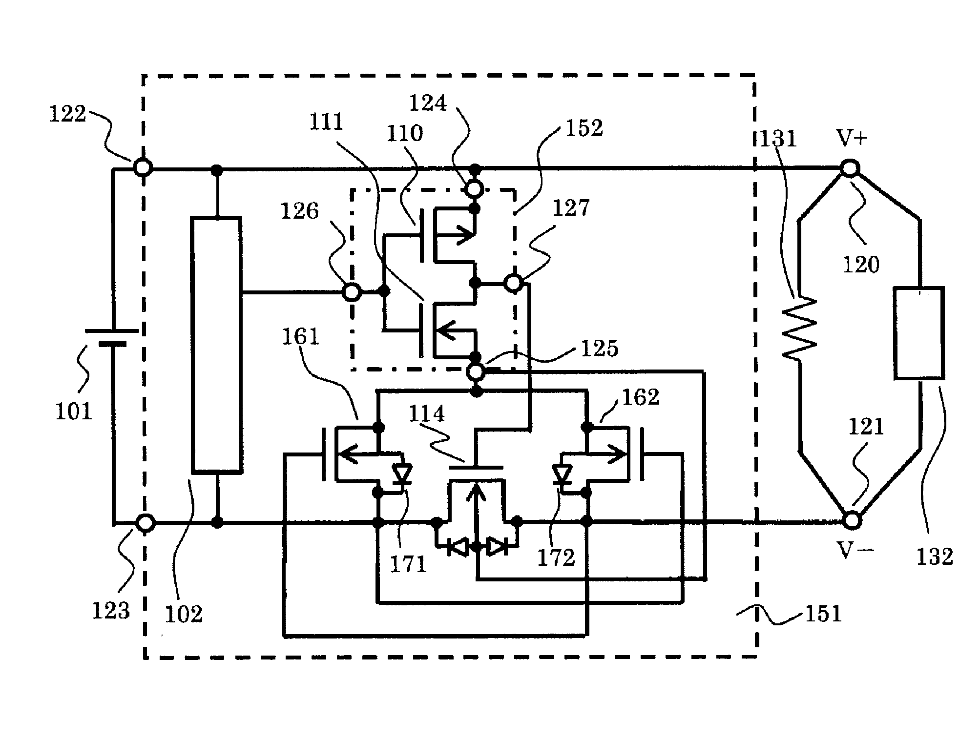
[0028]FIG. 1 is a circuit diagram illustrating a battery device including a charging and discharging control circuit 151 according to a first embodiment.
[0029]The battery device according to the first embodiment includes a secondary battery 101, a charging and discharging control circuit 151, and a V+ terminal 120 and a V− terminal 121 between which a charger 132 and a load 131 are connected. The charging and discharging control circuit 151 includes a control circuit 102, an N-channel bidirectional conduction type field effect transistor 114, a switching circuit 152, and NMOS transistors 161 and 162. The switching circuit 152 includes a PMOS transistor 110, an NMOS transistor 111, and terminals 124, 125, 126, and 127.
[0030]The secondary battery 101 is connected to a positive power supply terminal 122 and a negative power supply terminal 123. In the control circuit 102, a positive power supply is connected to the positive power supply terminal 122, a negative power supply is connecte...
second embodiment
[0039]FIG. 2 is a circuit diagram illustrating a battery device including a charging and discharging control circuit 251 according to a second embodiment.
[0040]The battery device according to the second embodiment includes a secondary battery 101, a charging and discharging control circuit 251, and a V+ terminal 120 and a V− terminal 121 between which a charger 132 and a load 131 are connected. The charging and discharging control circuit 251 includes a control circuit 102, a P-channel bidirectional conduction type field effect transistor 214, a switching circuit 152, and PMOS transistors 261 and 262. The switching circuit 152 includes a PMOS transistor 110, an NMOS transistor 111, and terminals 124, 125, 126, and 127.
[0041]The secondary battery 101 is connected to a positive power supply terminal 122 and a negative power supply terminal 123. In the control circuit 102, a positive power supply is connected to the positive power supply terminal 122, a negative power supply is connect...
PUM
 Abstract
Description
Claims
Application Information