Image capture apparatus and control method therefor

a technology of image capture and control method, which is applied in the field of image capture apparatus, can solve the problems of not being able to detect a translational motion in three directions (a motion parallel to the coordinate axes), lowering accuracy, and not being able to implement and cost reasons, so as to achieve accurate correction

Active Publication Date: 2015-03-26
CANON KK
View PDF4 Cites 36 Cited by
  • Summary
  • Abstract
  • Description
  • Claims
  • Application Information

AI Technical Summary

Benefits of technology

[0009]The present invention has been made in view of the above problems of conventional techniques. The present invention provides an image capture apparatus and a control method therefor, the image capture apparatus being capable

Problems solved by technology

These sensors, however, cannot detect a translational motion in three directions (a motion parallel to coordinate axes) and a rotational motion around a roll axis (optical axis) among six-degree-of-freedom motions of the image capture apparatus.
While the translational motion can be detected by providing an acceleration sensor as described in Japanese Patent Laid-Open No. 2010-25961, this is not easy for implementation and cost reasons.
However, a method for detecting and estimating an image distortion using a motion vector at the time of application of the geometric deformation processing lowers the accuracy depending on scenes, increases an amount of computation necessary for high-accuracy estimation, and makes the estimation itself difficult.
For example, in the case of a low-contrast image, such as an image captured indoors, it is more likely that a motion vector fail to be detected and an erroneous motion vecto

Method used


Image

  • Image capture apparatus and control method therefor
  • Image capture apparatus and control method therefor
  • Image capture apparatus and control method therefor

Examples


first embodiment

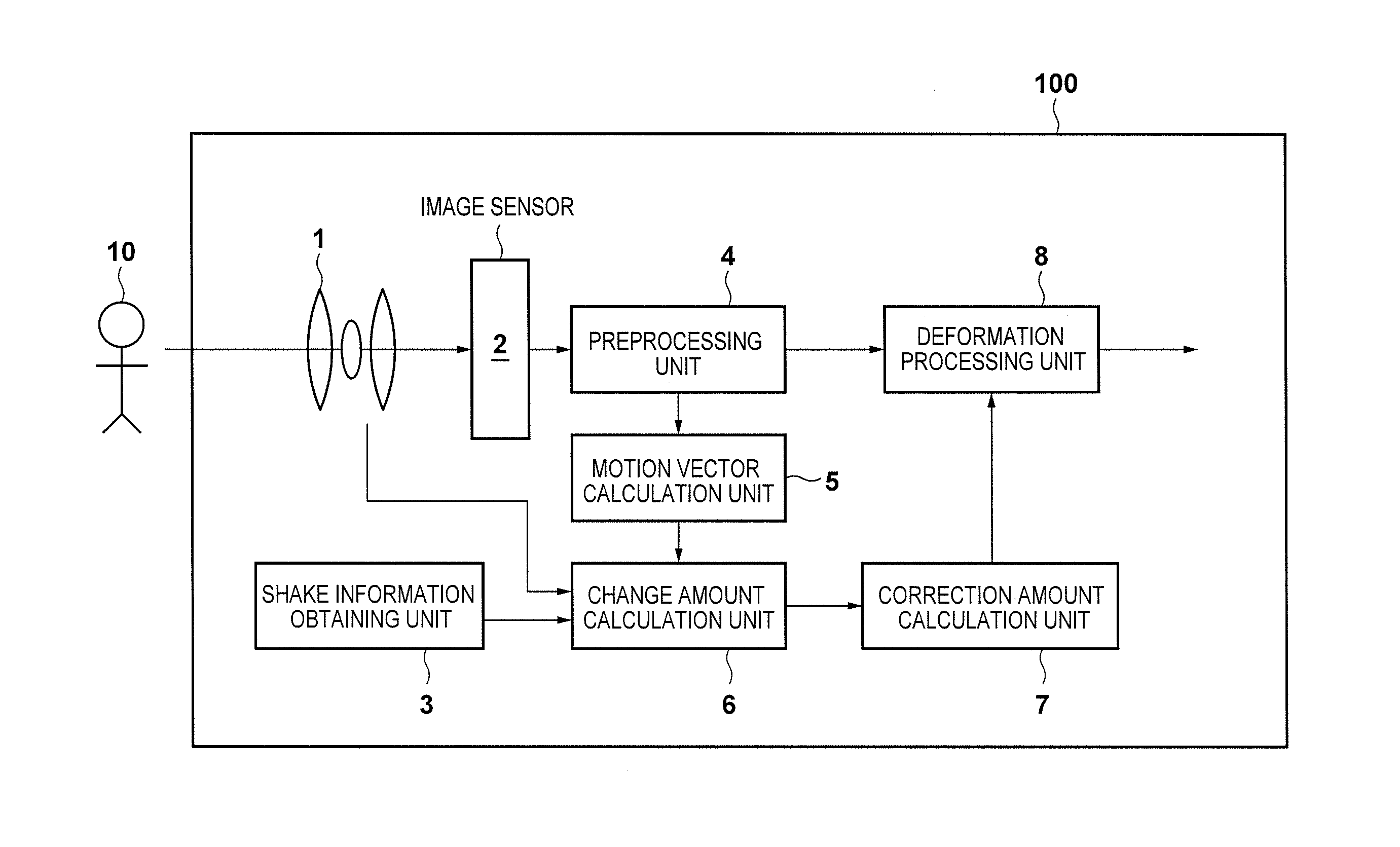
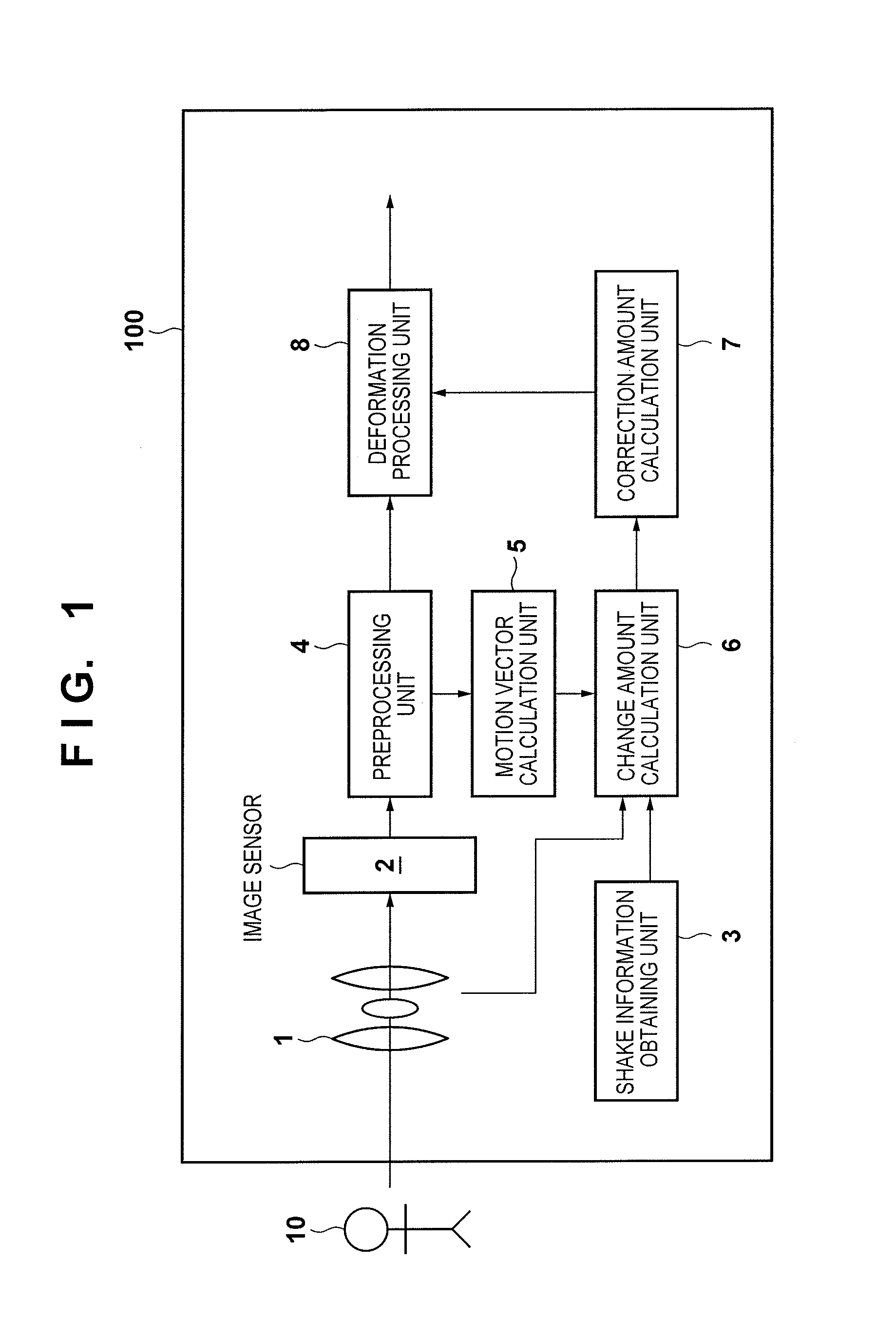
[0029]An exemplary embodiment of the present invention will now be described in detail with reference to the attached drawings. FIG. 1 shows an example of a functional configuration of a digital camera 100, which is one example of an image capture apparatus according to a first embodiment of the present invention, related to anti-shake control. In FIG. 1, a part of a configuration of a general digital camera that is not directly related to the present invention is omitted.

[0030]An optical system 1 is an imaging optical system that includes a plurality of lenses, such as a focus lens, and a mirror, and focuses incident light from a subject 10 onto an imaging plane of an image sensor 2. The image sensor 2, which is a CCD image sensor or a CMOS image sensor, is composed of a plurality of pixels that are two-dimensionally arrayed. It is assumed that the image sensor 2 according to the present embodiment is a CMOS image sensor as the present embodiment describes an example in which a rol...

second embodiment

[0137]The following describes a second embodiment of the present invention with reference to FIG. 10. FIG. 10 is a block diagram schematically showing an example of a functional configuration of a digital camera 200, which is one example of an image capture apparatus according to the second embodiment of the present invention. Constituents of the digital camera 200 that are similar to those of the first embodiment are given reference numerals similar to those of the first embodiment, and a description thereof is omitted.

[0138]An optical system 21 is an imaging optical system that includes a plurality of lenses, such as a focus lens and a shake correction lens 2011, and focuses incident light from a subject 10 onto an imaging plane of an image sensor 2. The image sensor 2, which is a CCD image sensor or a CMOS image sensor, is composed of a plurality of pixels that are two-dimensionally arrayed. The digital camera 200 has an optical anti-shake function for reducing a shake of an imag...


PUM


Abstract

An amount of change between images is calculated based on a motion vector between images obtained by an image sensor and on shake information related to a shake in a rotational direction around at least an axis perpendicular to an optical axis of an imaging optical system. Then, based on a shake correction amount determined based on the shake information and the amount of change, an image obtained by the image sensor is geometrically deformed. The amount of change is a shake component of the image capture apparatus in a direction perpendicular to the optical axis, and is calculated after cancelling at least one of a change between images caused by the shake in the rotational direction included in the shake information and a change between images caused by an influence of a difference between exposure periods of the image sensor.

Description

BACKGROUND OF THE INVENTION[0001]1. Field of the Invention[0002]The present invention relates to an image capture apparatus and a control method therefor, and in particular to an image capture apparatus with an anti-shake function and a control method therefor.[0003]2. Description of the Related Art[0004]Conventionally, a so-called image stabilization function is known that corrects (alleviates) a shake of a captured image (an image shake) caused by a movement of an image capture apparatus, and representative methods for realizing the image stabilization function include optical image stabilization and electronic image stabilization (Japanese Patent Laid-Open No. 2011-145604). The optical image stabilization is a method for reducing a movement of an image of a subject by moving optical elements such as a shift lens and an image sensor along a plane perpendicular to an optical axis based on a detected amount of shake of an image capture apparatus. On the other hand, the electronic im...

Claims


Application Information

Patent Timeline
IPC IPC(8): H04N5/232
CPCH04N5/23264H04N23/6811H04N23/6812H04N23/683H04N23/6845H04N23/687H04N5/2628
Inventor TSUBAKI, HIDETOSHI
Owner CANON KK
Why Eureka
Try Eureka