Cooling Of A Medical Instrument

Active Publication Date: 2015-03-26
KARL STORZ GMBH & CO KG
View PDF3 Cites 6 Cited by
  • Summary
  • Abstract
  • Description
  • Claims
  • Application Information

AI Technical Summary

Benefits of technology

The present invention aims to provide a better cooled medical instrument that can be easily cleaned and autoclaved.

Problems solved by technology

Heat dissipation by means of natural convection is therefore no longer sufficient in all cases.
A conventional fan or compressor, for forcing convection or a cooling flow of fluid, cannot readily be cleaned and autoclaved and is therefore not considered for use at many medical instruments.

Method used


Image

  • Cooling Of A Medical Instrument
  • Cooling Of A Medical Instrument
  • Cooling Of A Medical Instrument

Examples


Embodiment Construction

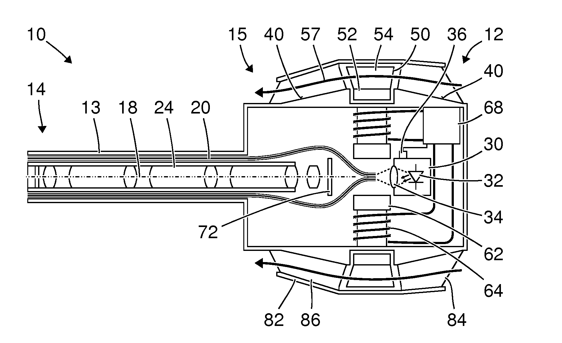
[0061]FIG. 1 shows a schematic view of an exoscope 10 with a proximal end 12 and a distal end 14. The exoscope 10 comprises a shaft 13, which in particular has a circular cylindrical or substantially circular cylindrical outer shape with an axis of symmetry 18. This axis of symmetry 18 is also referred to hereinbelow as the longitudinal axis of the exoscope 10. The exoscope 10 further comprises a handle 15 at the proximal end 12.

[0062]The view of the exoscope 10 in FIG. 1 is similar to a cross-sectional view. In contrast to a true cross-sectional view, a number of components and structural parts of the exoscope 10 are each indicated in plan view and section surfaces are not hatched.

[0063]The exoscope 10 comprises a hermetically tight sheath 20, which in particular is composed of a plurality of parts cohesively or coalescently joined to one another. Arranged inside the hermetically tight sheath 20 are optical fibers 22, by means of which illumination light generated by a light source...


PUM


Abstract

A medical instrument includes a hermetically tight sheath, a heat source, a surface area thermally coupled to the heat source, a rotor arranged outside the hermetically tight sheath and serving to generate a flow of fluid at the surface, a magnet at the rotor, and means for generating a variable magnetic field in order to move the rotor. The means for generating a variable magnetic field is arranged inside the hermetically tight sheath.

Description

FIELD OF THE INVENTION[0001]The present invention relates to an exoscope, an endoscope or another medical instrument, and in particular to the cooling of the medical instrument.BACKGROUND OF THE INVENTION[0002]Exoscopes, endoscopes and other medical instruments can contain image sensors, processors and other circuitry for processing image data and other data, power electronics, light-emitting diodes or other light sources and other heat sources. Normally, the thermal output generated by these heat sources is carried off mainly by natural convection, which is driven by the heating of the air surrounding the medical instrument. The continuing process of miniaturization of electronic components, their increasing performance and their availability at ever lower costs cause that medical instruments contain an increasing number of electronic components with increasing thermal output. Heat dissipation by means of natural convection is therefore no longer sufficient in all cases. A conventi...

Claims


Application Information

Patent Timeline
IPC IPC(8): A61B1/12A61B19/00A61B1/00A61B5/00
CPCA61B1/128A61B1/00006A61B19/5223A61B5/0077A61B1/002A61B1/0669A61B2090/306A61B2090/309A61B2090/3616G02B23/2476
Inventor CZUPALLA, CHRISTIANKUPFERSCHMID, MARKUSHENI, ANDREAS
Owner KARL STORZ GMBH & CO KG
Why Eureka
Try Eureka