Method of providing data for minimizing difference between dimensions of three-dimensional structure formed by laser radiation and design values of scan path of such three-dimensional structure and computer and computer program for providing such data

Inactive Publication Date: 2015-03-26
GLOBALFOUNDRIES INC
View PDF0 Cites 27 Cited by
  • Summary
  • Abstract
  • Description
  • Claims
  • Application Information

AI Technical Summary

Benefits of technology

[0023]Accordingly, another aspect of the present invention is a non-transitory computer program product for providing data for minimizing a difference between a plurality of dimensions of a three-dimensional structure formed by a laser radiation and a plurality of design values of a scan path of the three-dimensional structure, the computer program product including a computer readable storage medium having program instructions embodied therewith which, when executed, cause a computer device to perform the steps of a method including: modeling a manufacturing process of the three-dimensional structure and formulating a shrinkage of material used in the manufacturing process, in which a shrinkage function is formulated in the case where the material shrinks depending on a scan length xi of the scan path of the laser and in which the shrinkage function is represented by an Equation 1; and performing an optimization calculation for minimizing a difference between the dimensions of the three-dimensional structure after the shrinkage of the material and the design values by using the shrinkage model formulated according to the Equation 1 and computing a scan length x minimizing the difference; in which xi of the Equation 1 is the scan length of the scan path and s(l) of

Problems solved by technology

Accuracy of dimension is a technical proble

Method used


Image

  • Method of providing data for minimizing difference between dimensions of three-dimensional structure formed by laser radiation and design values of scan path of such three-dimensional structure and computer and computer program for providing such data
  • Method of providing data for minimizing difference between dimensions of three-dimensional structure formed by laser radiation and design values of scan path of such three-dimensional structure and computer and computer program for providing such data
  • Method of providing data for minimizing difference between dimensions of three-dimensional structure formed by laser radiation and design values of scan path of such three-dimensional structure and computer and computer program for providing such data

Examples


Embodiment Construction

Technical Problems

[0055]The accuracy of dimensions is a problem in the additive manufacturing technology field.

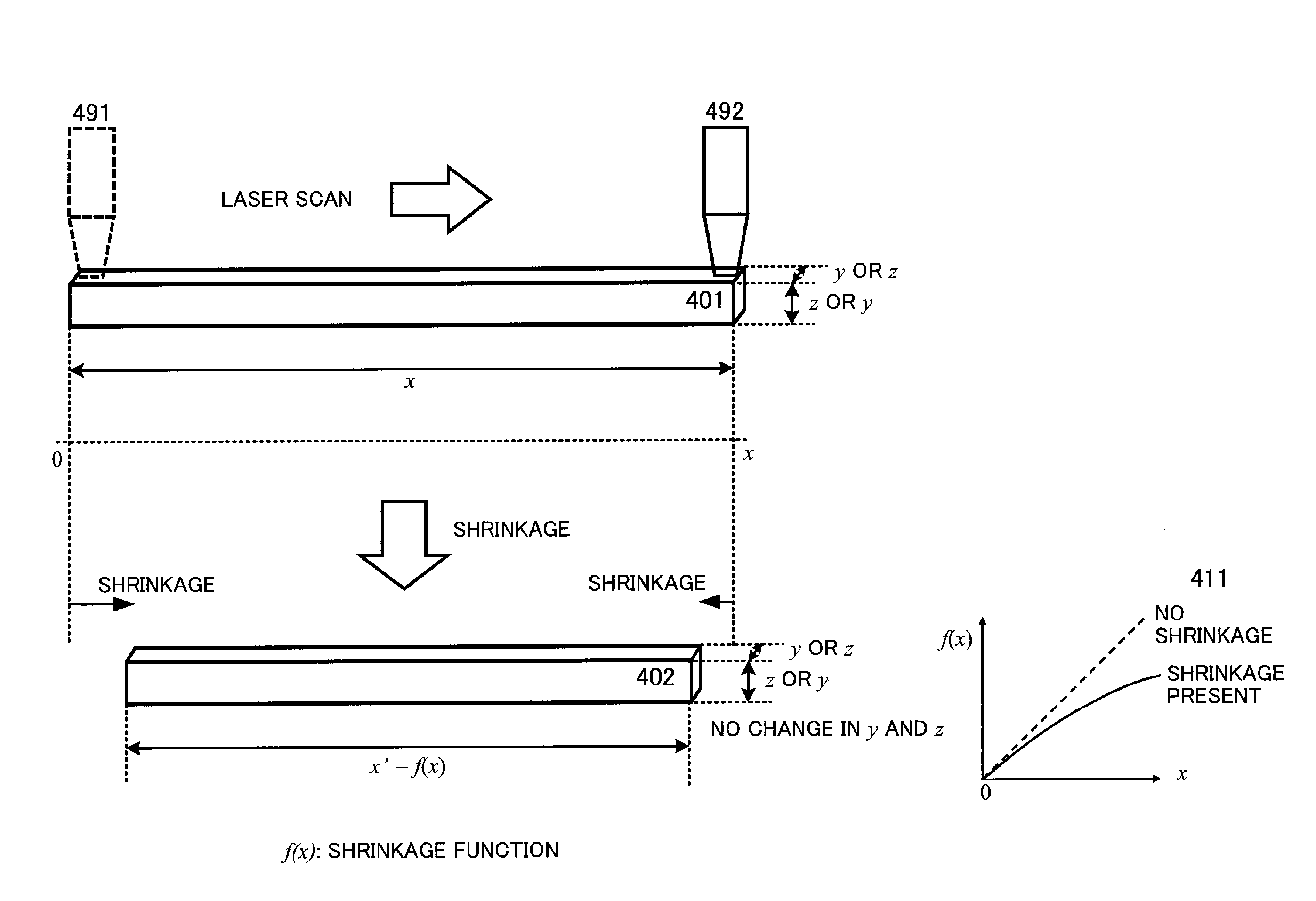
[0056]In the stereolithography, liquid photo-curable resin is irradiated with laser and cured one layer by one layer to form a three-dimensional structure. In performing the photo-curing, however, shrinkage of the aforementioned photo-curable resin, particularly partial shrinkage, occurs. Therefore, it is difficult to acquire an expected precision.

[0057]In the powder sintering shaping method, an arbitrary three-dimensional cross-sectional shape is scanned and irradiated with laser to sequentially fuse and sinter the resin, metal powder, and the like by using a heat source of the laser for lamination in order to form a three-dimensional structure. At the time of the laser radiation, the instantly-fused powder material inevitably settles down. Therefore, at the time of sintering, most of the shrinkage is naturally corrected by an excess curing unit in the z-axis direction (Re...


PUM

PropertyMeasurementUnit
Lengthaaaaaaaaaa
Thicknessaaaaaaaaaa
Shrinkageaaaaaaaaaa

Abstract

Acquiring expected precision even in a case that partial shrinkage occurs. The present invention is a technique for providing data for minimizing a difference between dimensions of a three-dimensional structure formed by laser radiation and design values of a scan path of the three-dimensional structure, in which the technique includes: modeling a manufacturing process of the three-dimensional structure and formulating a shrinkage of material used in the manufacturing process; and performing an optimization calculation for minimizing the difference between the dimensions of the three-dimensional structure after the shrinkage of the material and the design values by using the formulated shrinkage model to compute the scan length x minimizing the difference, and in which the formulation includes formulating a shrinkage function in the case where the material shrinks according to the scan length xi of the scan path of the laser.

Description

CROSS-REFERENCE TO RELATED APPLICATION[0001]This application claims priority under 35 U.S.C. §119 from Japanese Patent Application No. 2013-195370 filed Sep. 20, 2013, the entire contents of which are incorporated herein by reference.BACKGROUND OF THE INVENTION[0002]The present invention relates to a technique for providing data for minimizing a difference between the dimensions of a three-dimensional structure formed by laser radiation and the design values of a scan path of the three-dimensional structure.BACKGROUND ART[0003]An additive manufacturing (AM) technology was introduced to the world about 20 years ago. At that time, it attracted attention as a revolutionary technology capable of rapidly manufacturing a resin product model by way of trial without making a mold. Therefore, it has been also referred to as “rapid prototyping.”[0004]The additive manufacturing technology is capable of directly manufacturing a three-dimensional structure from three-dimensional CAD data and the...

Claims


Application Information

Patent Timeline
IPC IPC(8): G06F17/50B22F3/00B28B17/00B29C67/00B28B1/00
CPCG06F17/50B29C67/0088B29C67/0077B29K2105/251B28B17/0081B22F3/008B28B1/001G05B2219/49023B33Y50/00G06T19/20B29C64/386Y02P10/25B22F10/85B22F10/28B22F10/366B22F12/41B22F10/12
Inventor INOUE, TADANOBUKATAYAMA, YASUNAOSAKAMOTO, MASAHARU
Owner GLOBALFOUNDRIES INC
Why Eureka
Try Eureka