
Method for gas metal arc welding

a gas metal arc welding and gas technology, applied in the direction of welding/cutting media/materials, welding apparatus, manufacturing tools, etc., can solve the problems of toxic and/or carcinogenic, evaporation of constituents, and releasing extremely deleterious emissions, so as to achieve high economic viability, reduce health risks for welders, and high productivity of the gma welding method.

Active Publication Date: 2015-04-02
LINDE AG
View PDF6 Cites 3 Cited by
  • Summary
  • Abstract
  • Description
  • Claims
  • Application Information

AI Technical Summary

Benefits of technology

The invention relates to a new method for GMA welding that prevents the release of harmful emissions during the welding process. The method involves using a dead weld metal containing a harmful constituent that is fed to the arc and / or molten bath without a current. This dead weld metal is only melted by the heat of the arc or molten bath, resulting in no significant evaporation of the harmful constituent. The method also allows for greater freedom of movement with the GMA blowtorch or GMA welding device, without the need for additional wiring. The invention is geared toward fighting and preventing the evaporation of harmful constituents, reducing health risks to the welder. The economic viability and productivity of the GMA welding method are retained, and the method may even improve efficiency and reduce costs.

Problems solved by technology

However, melting the constituents can also cause the constituents to evaporate.
Evaporating the constituents releases extremely deleterious emissions, which in particular are toxic and / or carcinogenic.
The welder can at least partially breathe in these emissions, which poses a proven significant health risk.
However, suction burners are associated with major disadvantages.
Suction burners have a more cumbersome design and a greatly restricted accessibility.
Moreover, they are much harder to handle by the welder.
Furthermore, the extremely fine emission particles can often not be kept out by basic filters.
In addition to that, the emissions most frequently empty out close to the material surface, and are difficult, if not impossible, to detect with the suction burner.

Method used


Image

  • Method for gas metal arc welding
  • Method for gas metal arc welding
  • Method for gas metal arc welding

Examples


Embodiment Construction

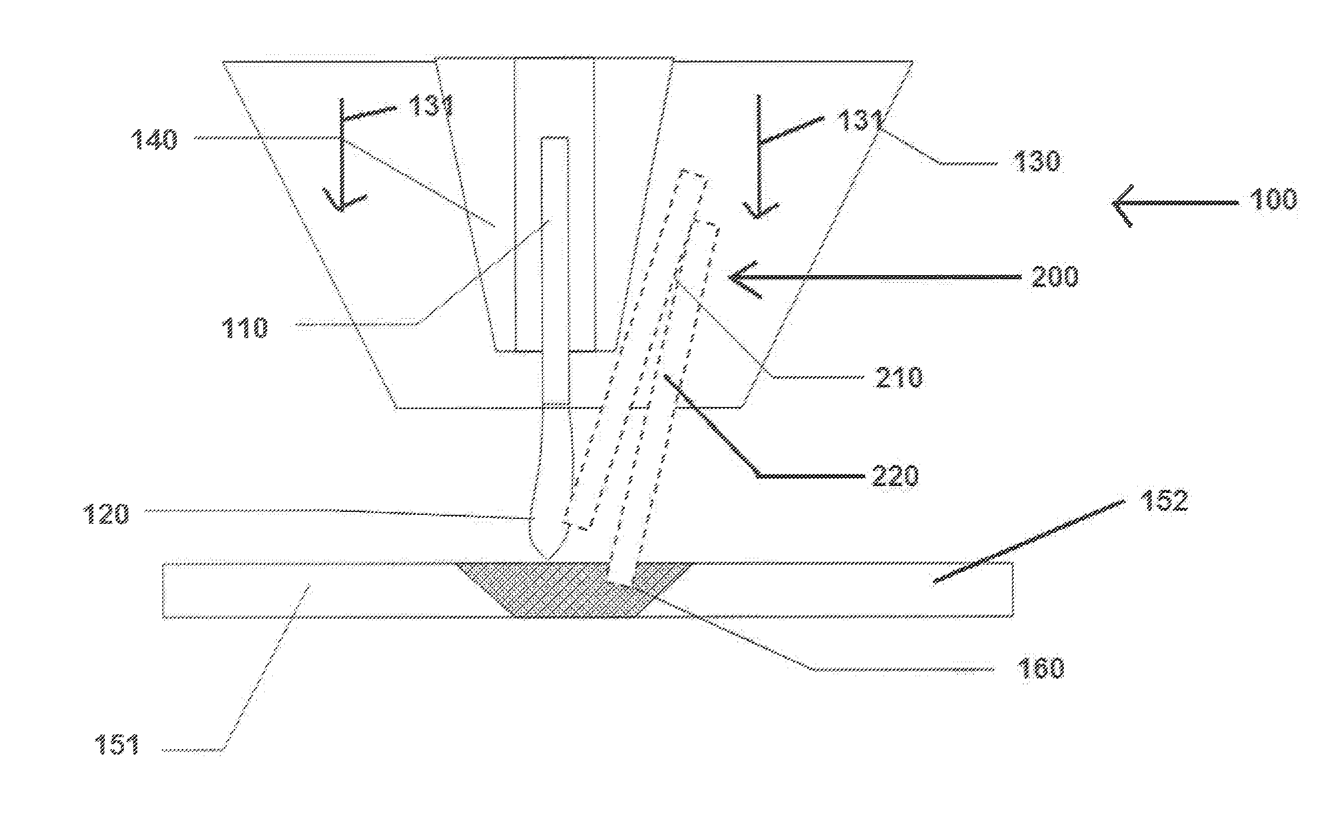
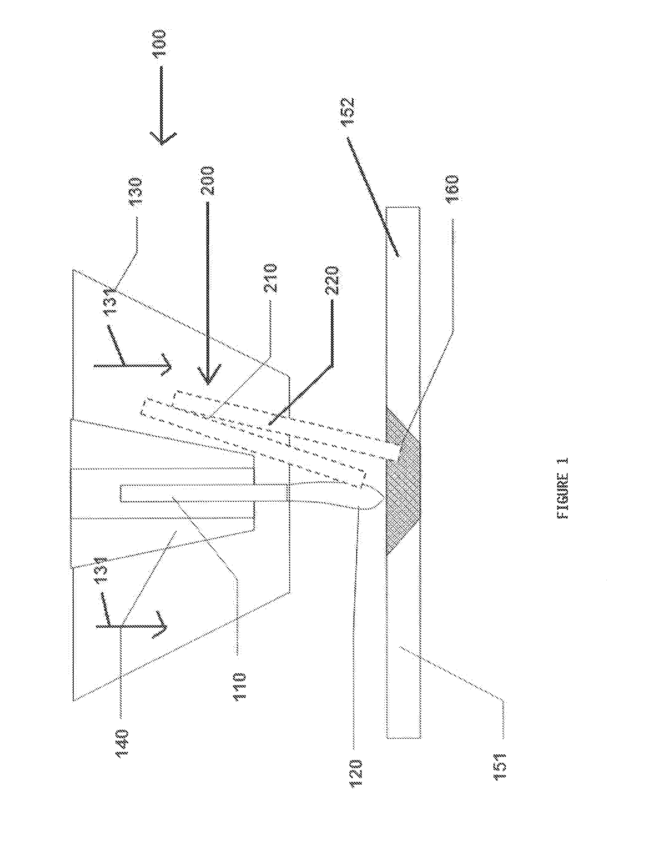
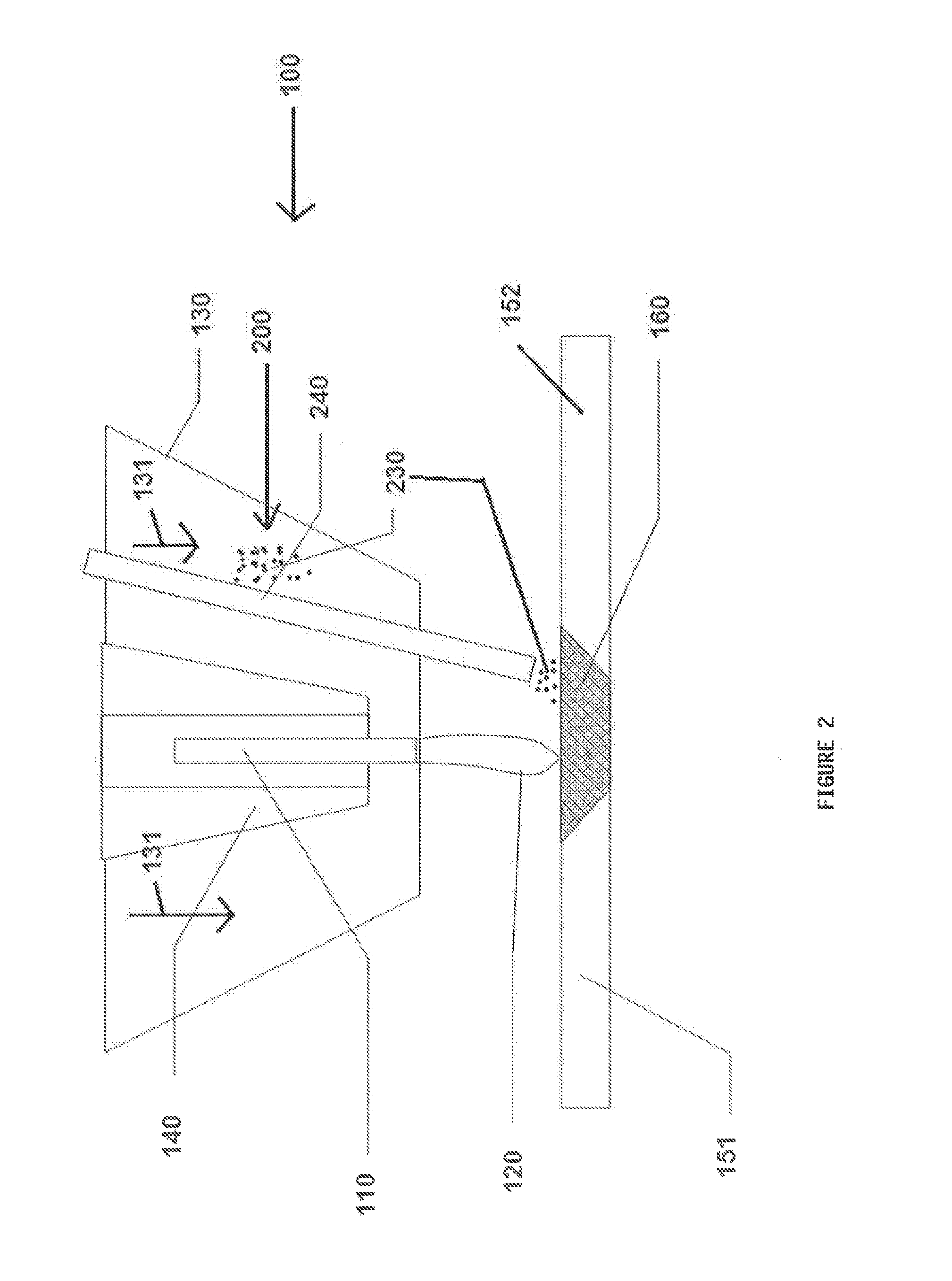
[0046]A gas metal arc welding device (GMA welding device) is schematically depicted in a respectively analogous manner on FIGS. 1 and 2 as a device for gas metal arc welding (GMA welding), and marked 100. Identical reference numbers on FIGS. 1 and 2 here relate to identical elements.

[0047]The GMAW welding device 100 is used in a joining process to weld a first work piece 151 with a second work piece 152. The GMAW welding device 100 exhibits a current-carrying wire electrode 110 in the form of a wire that is enveloped by a current contact sleeve 140. An electrical voltage is applied between the first work piece 151 and current contact sleeve 140 (not shown). Electrical current flows into the wire electrode 110 by way of the current contact sleeve 140. Therefore, the wire electrode 110 carries a current.

[0048]An arc 120 is initiated via contact ignition and burns between the current-carrying wire electrode 110 and first work piece 151. The high temperatures melt the tip of the wire el...


PUM

PropertyMeasurementUnit
Fractionaaaaaaaaaa
Fractionaaaaaaaaaa
Fractionaaaaaaaaaa

Abstract

A method and device for gas metal arc welding, wherein a current-carrying wire electrode is melted by an arc, and wherein gas metal arc welding is performed using a filler metal, which contains at least one constituent that releases deleterious emissions through evaporation, wherein a composition that does not contain this constituent is selected for the wire electrode, and a dead weld metal containing this constituent is fed to the arc and / or a molten bath without a current.

Description

CROSS REFERENCE TO RELATED APPLICATIONS[0001]This application claims priority from German patent application DE102013016452.4 Filed Oct. 2, 2013.BACKGROUND OF THE INVENTION[0002]The invention relates to a method and device for gas metal arc welding, wherein a current-carrying wire electrode is melted by an arc, and wherein gas metal arc welding is performed using a filler metal, which contains at least one constituent that releases deleterious emissions through evaporation.[0003]Gas metal arc welding (GMA welding) involves an arc welding method that is used for the overlay welding, welding or soldering of one, two or more work pieces made out of metal materials. In an inert gas atmosphere, a wire electrode is here continuously fed in the form of a wire or belt and melted by an arc that burns between the work piece and wire electrode. The work piece here serves as a second electrode. In particular, the work piece here serves as a cathode, and the wire electrode as an anode. The catho...

Claims


Application Information

Patent Timeline
IPC IPC(8): B23K9/173B23K9/12
CPCB23K9/124B23K9/1735B23K9/173B23K35/3053B23K35/0261
Inventor SIEWERT, ERWAN
Owner LINDE AG
Learn More