Electric Motor Control Device

a technology of electric motors and control devices, applied in the direction of motor/generator/converter stoppers, dynamo-electric gear control, dynamo-electric converter control, etc., to achieve the effect of reducing vibration further, reducing vibration further, and reducing the difficulty of calculation of estimated corrected rotation speed

Active Publication Date: 2015-04-02
CALSONIC KANSEI CORP +1
View PDF21 Cites 11 Cited by
  • Summary
  • Abstract
  • Description
  • Claims
  • Application Information

AI Technical Summary

Benefits of technology

[0019]According to the electric motor control device as recited in claim 1, the estimated corrected rotation speed calculation unit that takes the error as input suppresses the periodic speed fluctuation component included in the estimated rotation speed, so that vibration can be further reduced in a high frequency range when controlling an electric motor by position sensorless control.
[0020]According to the electric motor control device as recited in claim 2, by having the error be angle error, it is possible to calculate the estimated corrected rotation speed easily by using a peak filter or the like in the estimated corrected rotation speed calculation unit.
[0021]According to the electric motor control device as recited in claim 3, by configuring the estimated corrected rotation speed calculation unit with the first peak filter, it is possible to calculate the estimated corrected rotation speed easily.
[0022]According to the electric motor control device as recited in claim 4, by using the second peak filter for calculation of the rotation speed difference between the target rotation speed and the estimated corrected rotation speed, it is possible to reduce vibration further in an even higher frequency range.
[0023]According to the electric motor control device as recited in claim 5, by using the second peak filter that takes the rotation speed difference between the target rotation speed and the estimated corrected rotation speed as input, it is possible to reduce vibration further in an even higher frequency range.

Problems solved by technology

The above conventional electric motor control device, however, has the following problem.

Method used


Image

  • Electric Motor Control Device
  • Electric Motor Control Device
  • Electric Motor Control Device

Examples


embodiment 1

[0043]First, the overall structure of an electric motor control device according to Embodiment 1 of the present invention is described.

[0044]By performing position sensorless control, the electric motor control device of Embodiment 1 controls an Interior Permanent Magnet Synchronous Motor (IPMSM) that drives the compressor in an automobile air conditioner.

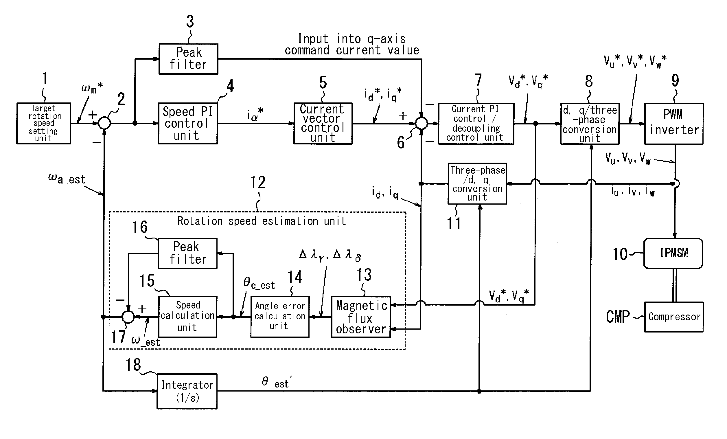
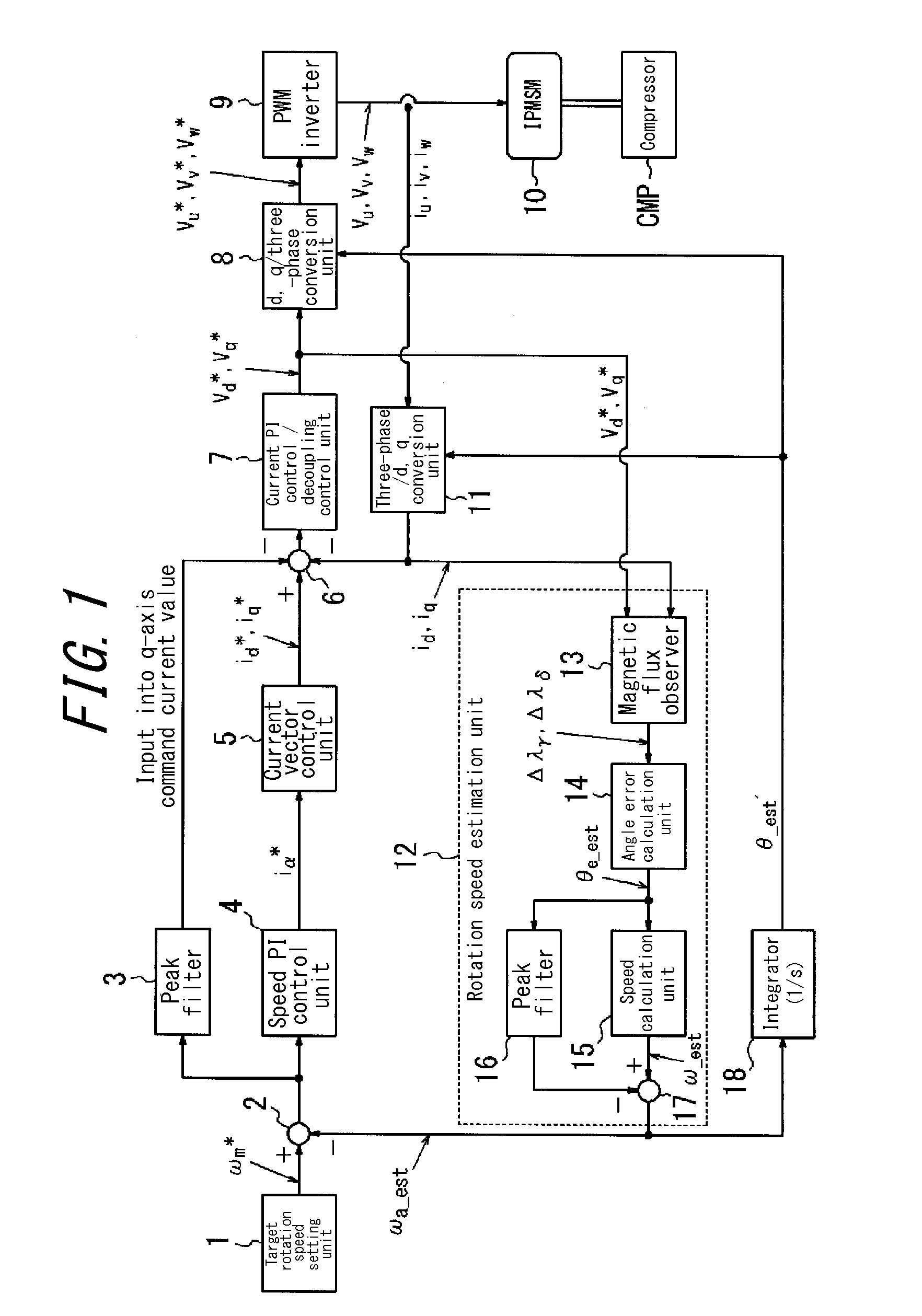
[0045]As illustrated in FIG. 1, the electric motor control device of Embodiment 1 includes a target rotation speed setting unit 1, a subtractor 2, a peak filter 3, a speed PI (proportional and integral) control unit 4, a current vector control unit 5, a subtractor 6, a current PI control / decoupling control unit 7, a d, q / three-phase conversion unit 8, and a Pulse Width Modulation (PWM) inverter 9. The PWM inverter 9 is connected to an IPMSM 10.

[0046]The output shaft of the IPMSM 10 is connected to a vane compressor CMP for an air conditioner, and the IPMSM 10 can drive the compressor CMP.

[0047]The electric motor control device of E...

embodiment 2

[0113]Next, Embodiment 2 is described. In the description of Embodiment 2, structural components similar to Embodiment 1 are not illustrated or are labeled with the same reference signs, and a description thereof is omitted. Only the differences are described.

[0114]The overall structure of an electric motor control device according to Embodiment 2 of the present invention is described based on the attached drawings.

[0115]The electric motor control device of Embodiment 2 differs from Embodiment 1 by not including the peak filter 3 of Embodiment 1, by the addition of a phase lead compensator 22, and by a resulting change to the subtractor 6.

[0116]In Embodiment 2, as illustrated in FIG. 8, a signal adjusted for phase and amplitude with respect to the rotation speed estimated value correction amount calculated in the peak filter 16 is used instead of the signal calculated by the peak filter 3 in Embodiment 1. The values calculated by the peak filters 16 and 3 are both signals generated ...


PUM


Abstract

An electric motor control device is capable of reducing vibration in a speed fluctuation range at a high frequency. The electric motor control device includes a target rotation speed setting unit that sets the target rotation speed of an electric motor, a rotation speed estimation unit that calculates an estimated rotation speed of the electric motor, and a drive command signal generation unit that generates a drive command signal for the electric motor so as to eliminate a rotation speed difference between the target rotation speed and the estimated rotation speed. The rotation speed estimation unit includes an error calculation unit that calculates an error related to rotation of the electric motor and an estimated corrected rotation speed calculation unit that calculates an estimated corrected rotation speed by taking the error as input and correcting the estimated rotation speed.

Description

TECHNICAL FIELD[0001]The present invention relates to an electric motor control device.BACKGROUND ART[0002]For example, when controlling a synchronous motor that drives an electric compressor in an automobile air conditioner, periodic speed fluctuation occurs as a result of torque fluctuation due to the compressor's compression cycle. Periodic speed fluctuation causes vibrations and noise. This phenomenon is prominent in a vane compressor, and periodic load fluctuation occurs in proportion to the number of vanes during the compression process. As a result, the speed fluctuation of the motor driving the compressor ends up increasing.[0003]Since such torque fluctuation in the compressor is periodic, methods such as a disturbance observer or repetitive control may be applied to reduce the torque fluctuation. In general, however, vibration becomes more difficult to suppress as the vibration frequency increases.[0004]On the other hand, electric motors have been controlled by detecting th...

Claims


Application Information

Patent Timeline
Patent Type & Authority Applications(United States)
IPC IPC(8): H02P6/06H02P6/00H02P21/00H02P27/04H02P21/13H02P21/18H02P21/24H02P23/12
CPCH02P6/002H02P6/06H02P21/141H02P2207/05H02P21/26H02P21/18H02P6/005
Inventor OSAMURA, KENSUKEOONEDA, YOUSUKEHIRATA, MITSUOSUZUKI, HAYATO
Owner CALSONIC KANSEI CORP
Why Eureka
Try Eureka