Color filter modules for plenoptic xyz imaging systems

a technology of plenoptic xyz imaging system and color filter module, which is applied in the field of design, can solve the problems of difficult to fabricate good xyz filter, difficult to fabricate xyz color filter at a size and pattern, and the less common xyz imaging system, so as to achieve the effect of convenient manufacturing and assembly

Inactive Publication Date: 2015-04-02
RICOH KK
View PDF32 Cites 44 Cited by
  • Summary
  • Abstract
  • Description
  • Claims
  • Application Information

AI Technical Summary

Benefits of technology

[0008]The use of a plenoptic imaging system overcomes some of the difficulties of manufacturing XYZ color filters to be placed over a sensor array. A plenoptic XYZ imaging system includes two overlapping imaging systems: a primary imaging subsystem and a secondary imaging array (e.g., a microlens array). The secondary imaging array is placed at the image plane of the primary imaging subsystem. A sensor array is placed at the image plane of the secondary imaging array. A color filter module is placed at a conjugate plane of the sensor array. The sensor array then captures multiplexed XYZ images of the object, as filtered by the color filter module. Since the color filter module is placed at a conjugate plane of the sensor array, it can be much larger and therefore easier to manufacture and assemble.

Problems solved by technology

However, it is difficult to fabricate good XYZ filters and even more difficult to fabricate XYZ color filters at a size and in a pattern that can be placed over a sensor array.
As a result, XYZ imaging systems are not so common, despite the advantages of the XYZ color space.
However, due to effects such as noise introduced by the sensor array and variations in the manufacture and assembly of optical systems, use of the ΔE metric alone may be inadequate to evaluate the performance of a color imaging system.

Method used


Image

  • Color filter modules for plenoptic xyz imaging systems
  • Color filter modules for plenoptic xyz imaging systems
  • Color filter modules for plenoptic xyz imaging systems

Examples


Embodiment Construction

[0024]The figures and the following description relate to preferred embodiments by way of illustration only. It should be noted that from the following discussion, alternative embodiments of the structures and methods disclosed herein will be readily recognized as viable alternatives that may be employed without departing from the principles of what is claimed.

[0025]System Overview.

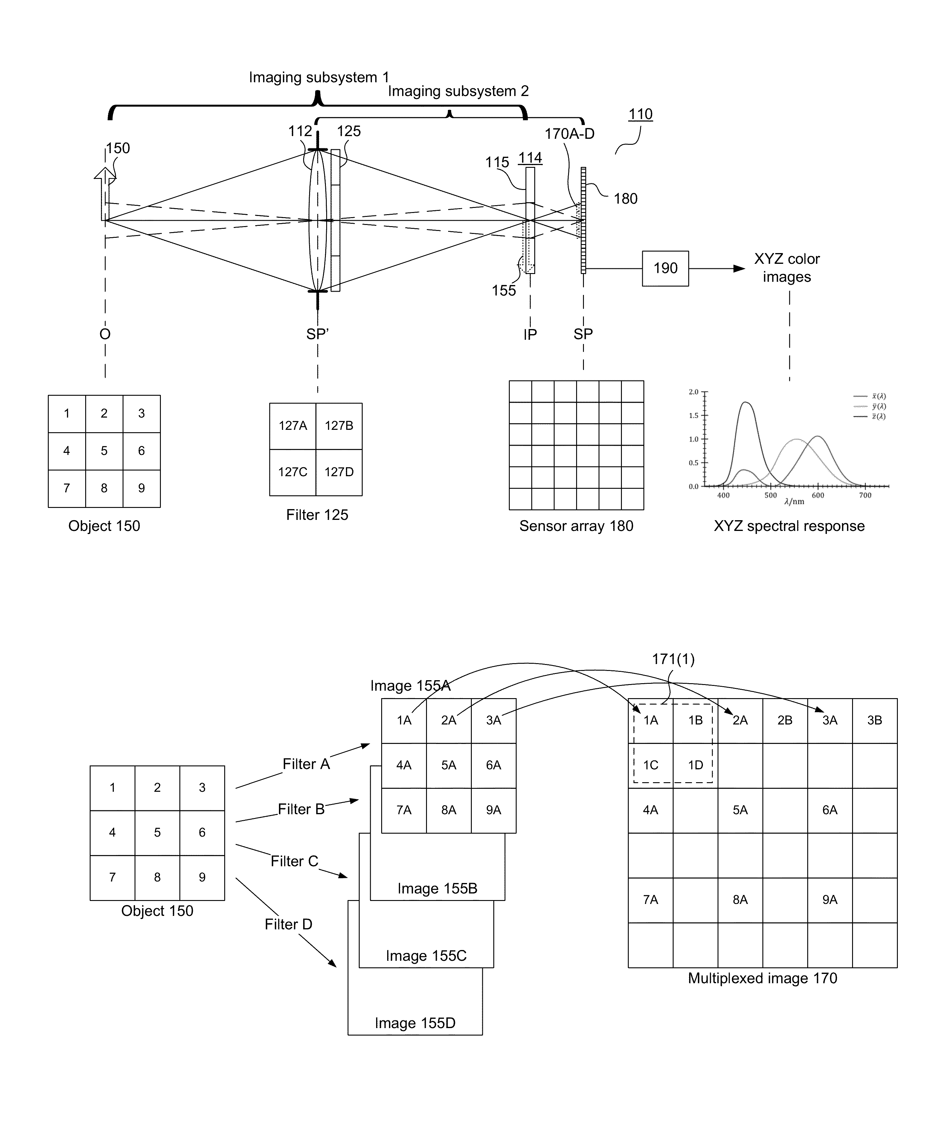
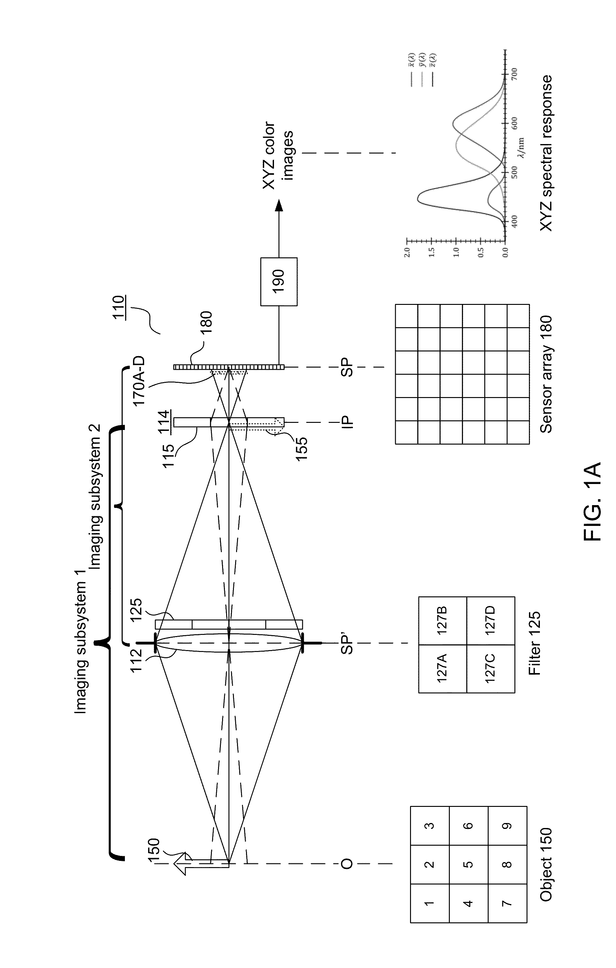
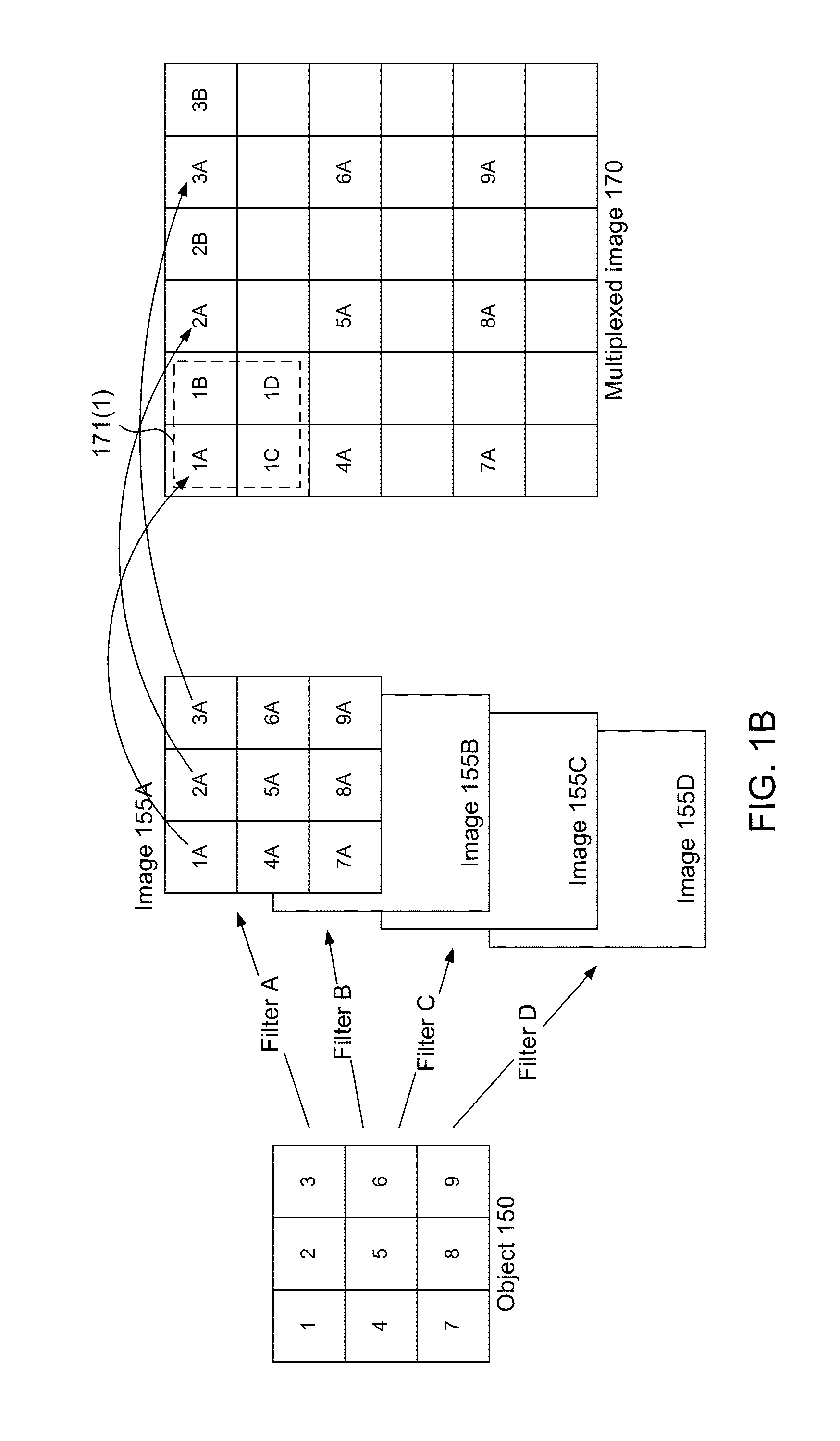
[0026]FIGS. 1A-1B are diagrams illustrating an example plenoptic XYZ imaging system according to the invention. The plenoptic XYZ imaging system 110 includes a primary imaging subsystem 112 (represented by a single lens in FIG. 1A), a secondary imaging array 114 (an array of image forming elements 115) and a sensor array 180. The secondary imaging array 114 may be referred to as a microimaging array. These form two overlapping imaging subsystems, shown as subsystem 1 and subsystem 2 in FIG. 1A.

[0027]For convenience, the optical imaging group 112 is depicted in FIG. 1A as a single objective lens, but it sh...


PUM


Abstract

A method for designing a color filter module used in a plenoptic XYZ imaging system. In one approach, the color filter module is spatially partitioned into filter cells, and the spatial partition is designed by considering data captured at the sensor in light of variations in ΔE.

Description

BACKGROUND OF THE INVENTION[0001]1. Field of the Invention[0002]This invention relates generally to the design of color filter modules in plenoptic XYZ imaging systems.[0003]2. Description of the Related Art[0004]Color filters are commonly used in order to enable color imaging. For example, the Bayer filter is a common arrangement of red, green and blue filters placed directly over a sensor array in order to create RGB imaging systems. The CIE XYZ color space is another formulation of color that has advantage over the more commonly used RGB color space. One advantage of an imaging system using XYZ filters is that the spectral sensitivities of the X, Y, and Z filters are much closer to the CIE standard observer color matching functions (the red, green and blue curves that represent an average human's chromatic response) than those of the R, G, and B filters used in conventional RGB imaging systems. As a result, an XYZ imaging system can reproduce these XYZ values more accurately than...

Claims


Application Information

Patent Timeline
Patent Type & Authority Applications(United States)
IPC IPC(8): H04N9/09H04N5/235
CPCH04N5/2355H04N9/09G01J3/513G01J2003/2826G01J2003/2806G02B5/201G01J3/462G01J2003/466G01J2003/1239G01J3/0208H04N25/447H04N25/135
Inventor MENG, LINGFEIBERKNER, KATHRINTOSIC, IVANA
Owner RICOH KK
Why Eureka
Try Eureka