
System for automatic power estimation adjustment

Active Publication Date: 2015-04-09
SIEMENS GAMESA RENEWABLE ENERGY AS
View PDF1 Cites 10 Cited by
  • Summary
  • Abstract
  • Description
  • Claims
  • Application Information

AI Technical Summary

Benefits of technology

The objective of this patent is to find a better way to estimate the amount of power available, without the problems of previous methods.

Problems solved by technology

The reduced power set-point avoids a situation in which the wind turbines would collectively generate more power than is consumed in the electricity network or grid, which would result in an undesirable increase in frequency of the generated power.
However, wind turbine revenue is generally based on the power that could be delivered by the wind turbine to the grid, i.e. the “available power” of that wind turbine, i.e. the wind turbine revenue may not necessarily be based on the power that is in fact delivered by the wind turbine to the grid.
However, the estimation of available power may be quite imprecise, since it is difficult to measure wind speed over the rotor plane with any degree of accuracy.
Wind gusts and turbulence (particularly in the case of a wind turbine that is downstream from another wind turbine) result in poor quality wind speed measurements.
Furthermore, even if an anemometer is located directly on a wind turbine, for example on its nacelle, it may not be able to provide an exact measurement for the wind speed at that turbine.
However, such an adjustment procedure is complex, and takes some time to be carried out.
Furthermore, since this approach requires manual intervention and because many factors must be considered, it is relatively easy for errors to accumulate, resulting in a sub-optimal control of the wind turbine.
Another problem can arise when the control of a wind turbine is adjusted to reduce the level of noise, particularly the aerodynamic noise caused by the rotor blades.
If the rotational velocity is reduced on the basis of an incorrect estimated wind speed value, the wind turbine may be operated at a low level of efficiency as a result.

Method used


Image

  • System for automatic power estimation adjustment
  • System for automatic power estimation adjustment
  • System for automatic power estimation adjustment

Examples


Embodiment Construction

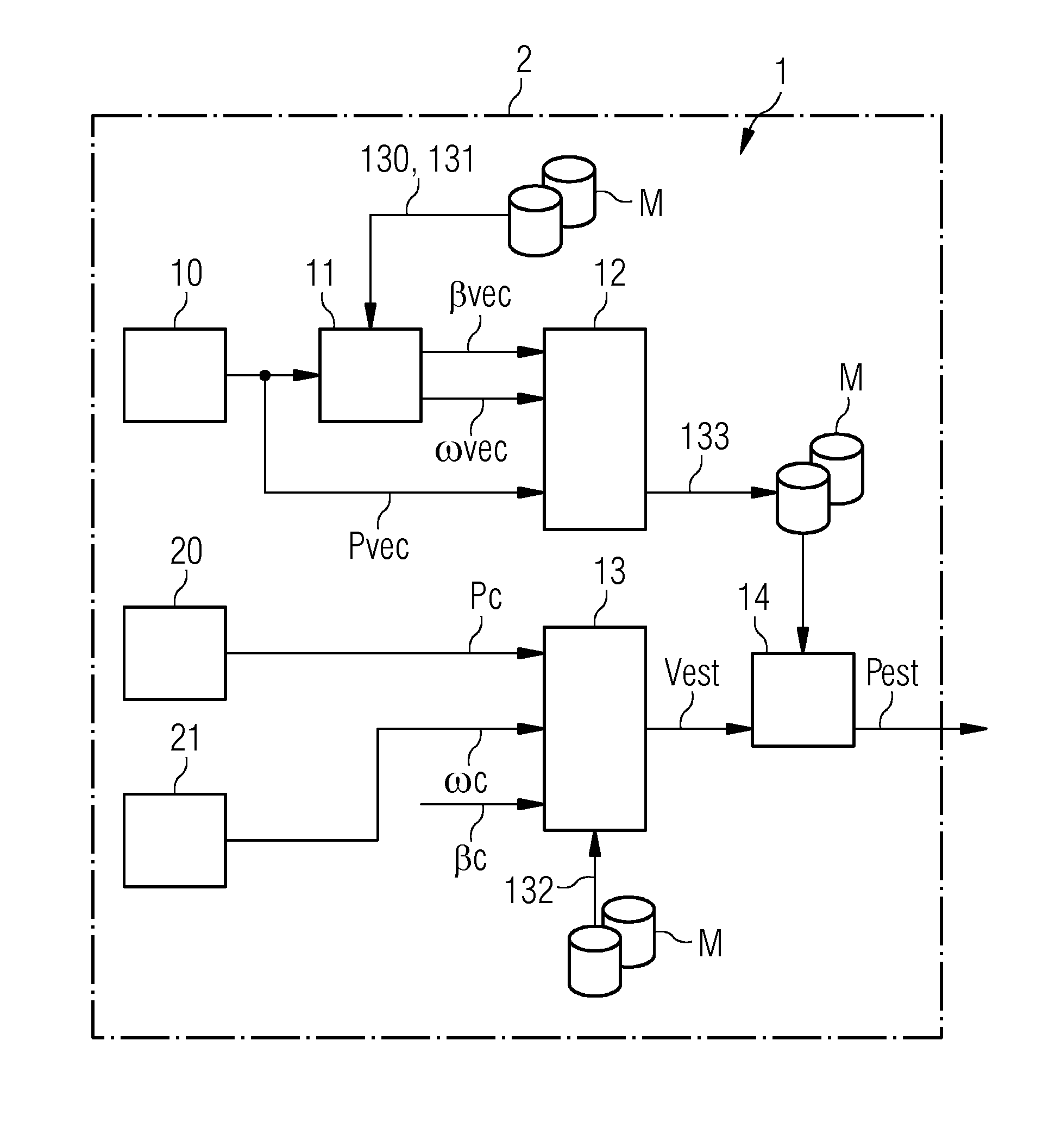
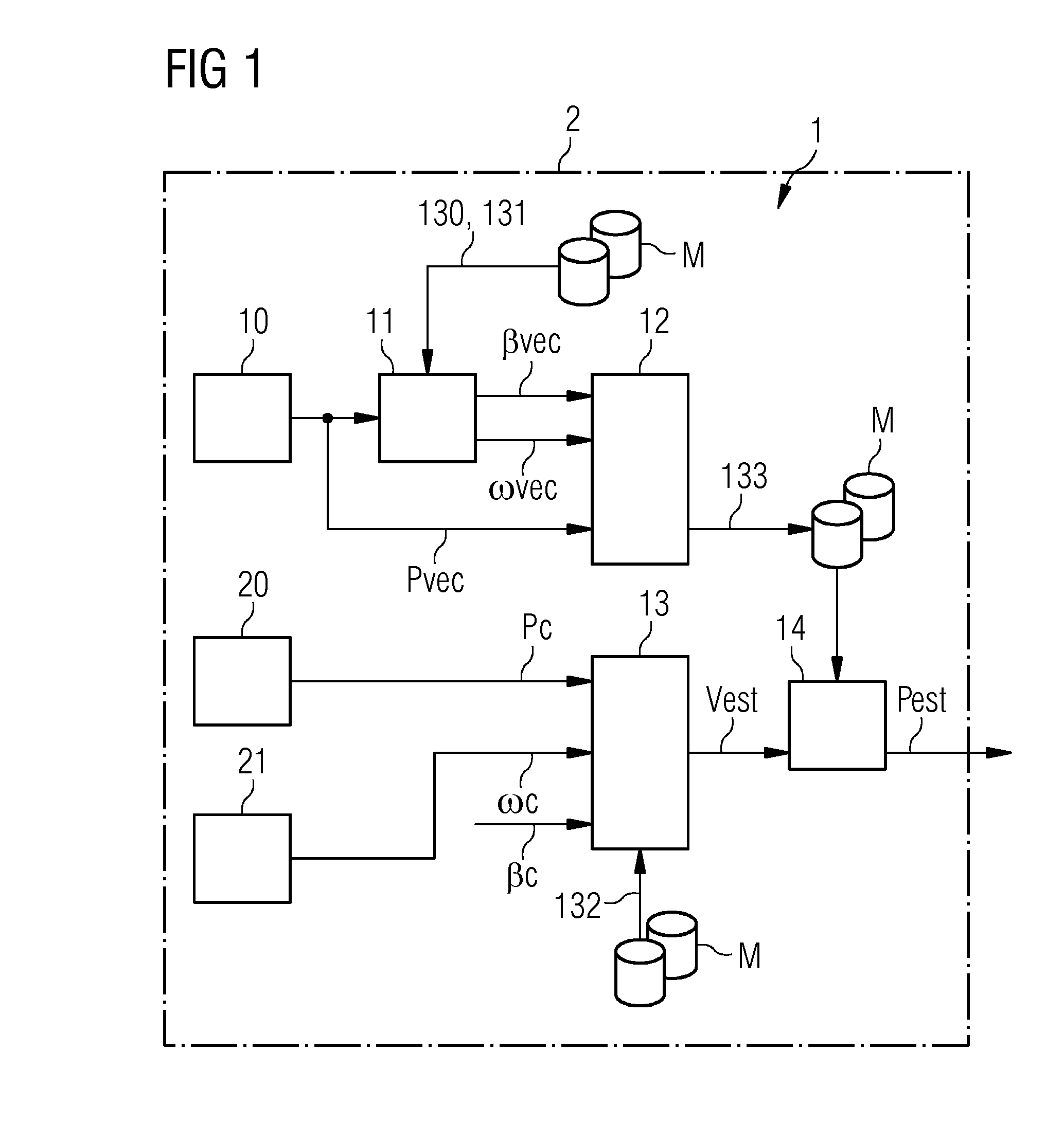
[0039]FIG. 1 shows a block diagram of an automatic adjustment system 1, for the automatic estimation of available power, according to an embodiment of the invention. This is shown as part of a wind turbine 2, for example the automatic adjustment system 1 can be realised as one or more modules of a computer program to be run on a processor or computer of the wind turbine 2. In this exemplary embodiment, the automatic adjustment system 1 comprises various memory modules M for storing data relating to the wind turbine 2. Here, the memory modules M store one or more speed / power curves, pitch curves, rpm / pitch data sets, and power curves.

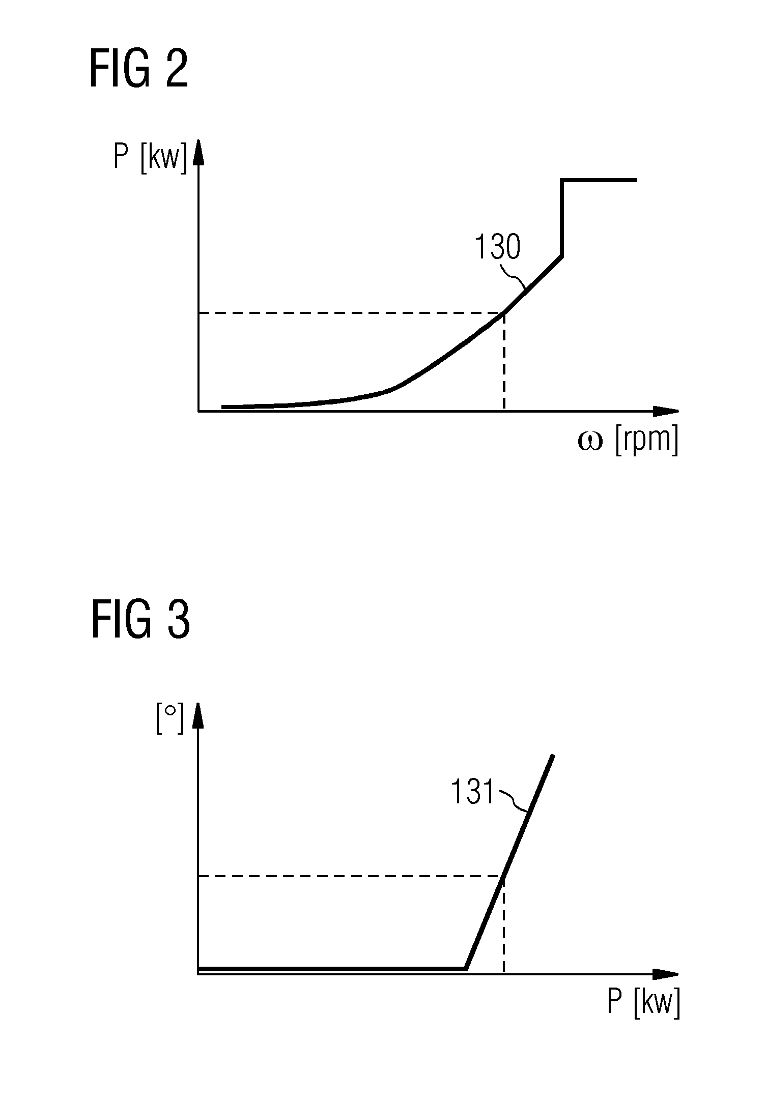
[0040]The automatic adjustment system 1 comprises a power vector generator 10 for generating a power vector Pvec of the wind turbine 2. The power vector Pvec is forwarded to a mapping block 11 or look-up block 11 realised to interpret one or more speed / power curves 130 and pitch curves 131 to determine a pitch vector βvec comprising a set of values corre...


PUM


Abstract

An automatic adjustment system for a variable-speed wind turbine is provided, having a power vector generator for generating a power vector (Pvec) of wind turbine output power; a mapping unit for establishing relationships (βvec, ωvec) between wind turbine output power and rotational speed and pitch angle on the basis of the power vector (Pvec) and an operational trajectory of the wind turbine; a wind speed estimator for estimating a wind speed (vest); an available power calculator for calculating the available power (Pest) of the wind turbine on the basis of the estimated wind speed (vest) and the established relationships (βvec, ωvec). A method of performing automatic analysis of a wind turbine configuration, a computer program product for carrying out the steps of such a method, and a wind turbine having such an automatic adjustment system are also provided.

Description

CROSS REFERENCE TO RELATED APPLICATIONS[0001]This application claims priority to and the benefit of European Application No. EP13187918 filed Oct. 9, 2013, incorporated by reference herein in its entirety.FIELD OF INVENTION[0002]The invention describes an automatic adjustment system for a variable-speed wind turbine, a method of performing automatic adjustment of an available power estimation of a variable-speed wind turbine; a computer program product; and a wind turbine.BACKGROUND OF INVENTION[0003]The wind turbines of a wind park can be operated at a reduced power set-point to ensure a satisfactory balance between the power being delivered by the wind turbines to the electricity network and the power being consumed in the electricity network. The reduced power set-point avoids a situation in which the wind turbines would collectively generate more power than is consumed in the electricity network or grid, which would result in an undesirable increase in frequency of the generated...

Claims


Application Information

Patent Timeline
IPC IPC(8): F03D7/00F03D9/00H02P9/04
CPCF03D7/00F03D9/005H02P9/04F05B2270/32F05B2260/821F03D9/257F03D7/04Y02E10/72F03D9/25
Inventor ESBENSEN, THOMASKRISHNA, RAMAKRISHNANSCHEURICH, FRANKSTOETTRUP, MICHAEL
Owner SIEMENS GAMESA RENEWABLE ENERGY AS
Learn More