
Method of controlling phase-shift full-bridge converter in light load operation

a full-bridge converter and phase-shift technology, applied in the direction of electric variable regulation, process and machine control, instruments, etc., can solve the problems of reducing increasing the switching loss of the power switch components, and increasing the switching loss of the conversion efficiency of the switching power converter

Active Publication Date: 2015-04-09
CHICONY POWER TECH CO LTD
View PDF6 Cites 26 Cited by
  • Summary
  • Abstract
  • Description
  • Claims
  • Application Information

AI Technical Summary

Benefits of technology

The present invention provides a method for controlling a phase-shift full-bridge converter in a light load operation. This method detects the magnetizing current of the transformer in the converter and switches control modes accordingly to solve problems of reduced efficiency in the converter. The method includes an extended control mode, a modified control mode, and an optimal degree of soft driving mode. The technical effect of this method is to improve the efficiency and performance of the phase-shift full-bridge converter in light load operation.

Problems solved by technology

However, the power switch components of the power converter withstand higher switching stresses and also produce more switching losses, once the switching frequency is increased, thus reducing the conversion efficiency of the switching power converter.
Because the conventional switching power converter is operated by the hard switching technology, the switching losses of the power switch components are also with increased if the switching frequency is increased.
Therefore, the switching losses would reduce the conversion efficiency, shorten the use life of the switch components, and increase the occupied space and costs of the additional heat-dissipating devices.
In addition, the voltage or current surge produced due to the non-ideal switching behavior causes the electromagnetic interference (EMI).

Method used


Image

  • Method of controlling phase-shift full-bridge converter in light load operation
  • Method of controlling phase-shift full-bridge converter in light load operation
  • Method of controlling phase-shift full-bridge converter in light load operation

Examples


Embodiment Construction

[0020]Reference will now be made to the drawing figures to describe the present invention in detail.

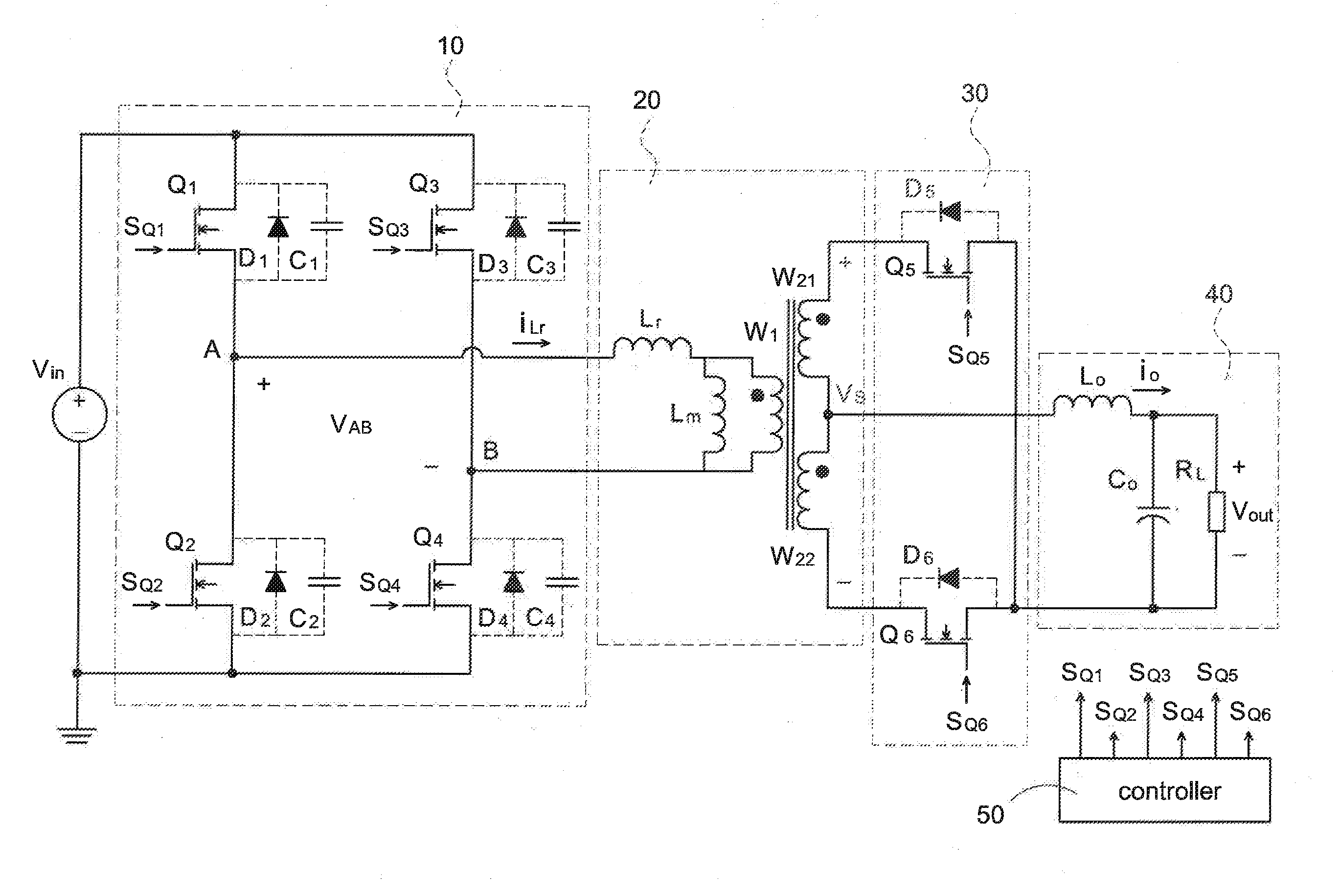
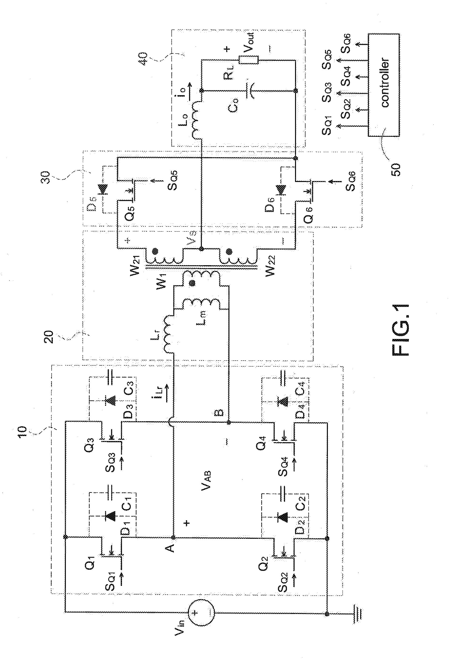
[0021]Reference is made to FIG. 1 which is a circuit diagram of a phase-shift full-bridge converter (PSFB converter) according to the present disclosure. The PSFB converter is electrically connected to a DC input voltage Vin and deliver the energy produced from the DC input voltage Vin to a rear-end load RL. The PSFB converter mainly includes a full-bridge switching circuit 10, a transformer 20, a synchronizing rectifier circuit 30, and a filter circuit 40.

[0022]The full-bridge switching circuit 10 has four power switches, namely, a first power switch Q1, a second power switch Q2, a third power switch Q3, and a fourth power switch Q4 to convert the DC input voltage Vin into a square-wave voltage. In particular, each of the power switches has a parasitic diode and a parasitic capacitance which are connected in parallel to the power switch. That is, the first power switch Q1 is connecte...


PUM


Abstract

A method of controlling a phase-shift full-bridge (PSFB) converter in a light load operation is provided to switch control modes of the PSFB converter by detecting magnetizing current of a transformer thereof. The method includes following steps: First, the PSFB converter is operated in an extended PSFB control mode when the magnetizing current is larger. Afterward, the PSFB converter is operated in a modified PSFB control mode when the magnetizing current is gradually reduced and electric charges transported by the residual magnetizing current near to or less than a half of the DC input voltage. Finally, the optimal degree of soft switching of the PSFB converter is implemented when the PSFB converter is operated at the modified PSFB control mode. Accordingly, it is to improve overall efficiency, reduce switching losses, and achieve electromagnetic compatibility.

Description

BACKGROUND[0001]1. Technical Field[0002]The present disclosure relates generally to a method of controlling a phase-shift full-bridge converter, and more particularly to a method of controlling a phase-shift full-bridge converter in a light load operation.[0003]2. Description of Related Art[0004]With the development of the semiconductor technology, the trend of designing small, short, thin, and light electronic products is necessary. For the power electronic products, the switching frequency is continually increased in order to effectively reduce volume and weight of the switching power converter. However, the power switch components of the power converter withstand higher switching stresses and also produce more switching losses, once the switching frequency is increased, thus reducing the conversion efficiency of the switching power converter.[0005]Because the conventional switching power converter is operated by the hard switching technology, the switching losses of the power swi...

Claims


Application Information

Patent Timeline
Patent Type & Authority Applications(United States)
IPC IPC(8): H02M3/335H02M1/00
CPCH02M3/3353H02M3/33507H02M1/0006H02M1/0009Y02B70/10H02M1/0054
Inventor WU, ZHEN-YUANLEUNG, TIM-CHEUNG
Owner CHICONY POWER TECH CO LTD
Learn More