Vehicle braking/driving force control apparatus

Active Publication Date: 2015-04-09
TOYOTA JIDOSHA KK
View PDF2 Cites 5 Cited by
  • Summary
  • Abstract
  • Description
  • Claims
  • Application Information

AI Technical Summary

Benefits of technology

[0016]As a result, the control part can use the gain that can be determined depending on the slip state amount and the magnitude of the driving force or the braking force on the slipping wheel to increase or decrease the target motion state amounts for controlling the motions of the body in the vehicle vertical direction, specifically, the roll motion and the pitch motion (or heave motion) that do not directly relate to the travel stability but closely relate to the ride comfort. In this way, the gain can be determined depending on the slip state amount and the magnitude of the driving force or the braking force on the slipping wheel, thereby appropriately reflecting the slip state to increase or decrease the target motion state amounts for controlling the motions of the body in the vehicle vertical direction. As a result, the influence caused by the occurrence of the slipping wheel can be more appropriately eliminated, and the control part can continue the control of the motions in the vehicle longitudinal and lateral directions by priority to excellently secure the travel stability or the steering stability of the vehicle.
[0017]Moreover, the control part can determine an increase or a decrease of the gain in a direction in which the driving force or the braking force suppres

Problems solved by technology

Therefore, for example, when a slip occurs on at least one wheel among all the wheels (all the driving wheels), the driving force or the braking force distributed as described above cannot be generated on the wheel on which the slip is occurring.
As a result, the target longitudinal

Method used


Image

  • Vehicle braking/driving force control apparatus
  • Vehicle braking/driving force control apparatus
  • Vehicle braking/driving force control apparatus

Examples


Embodiment Construction

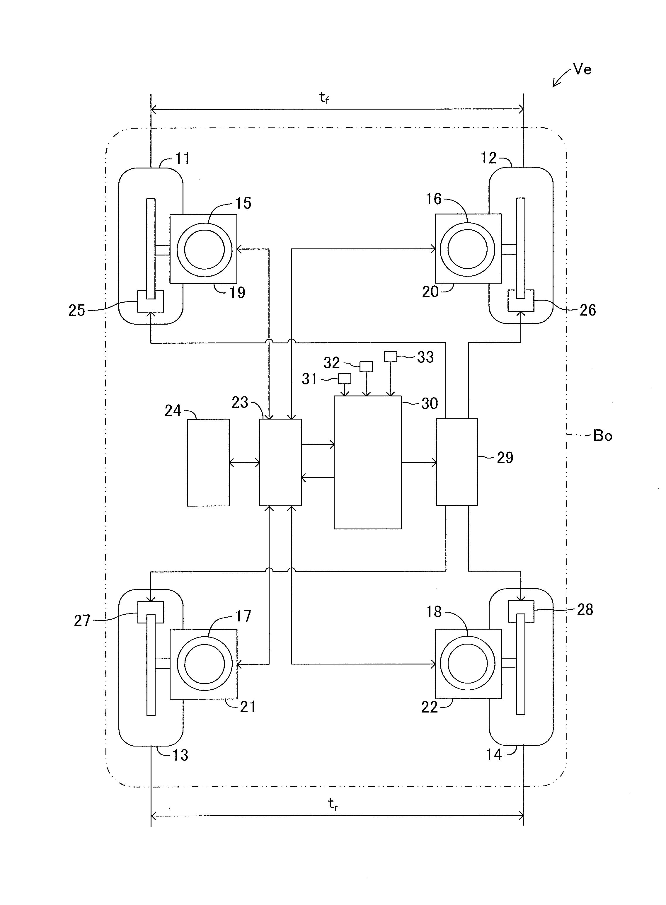
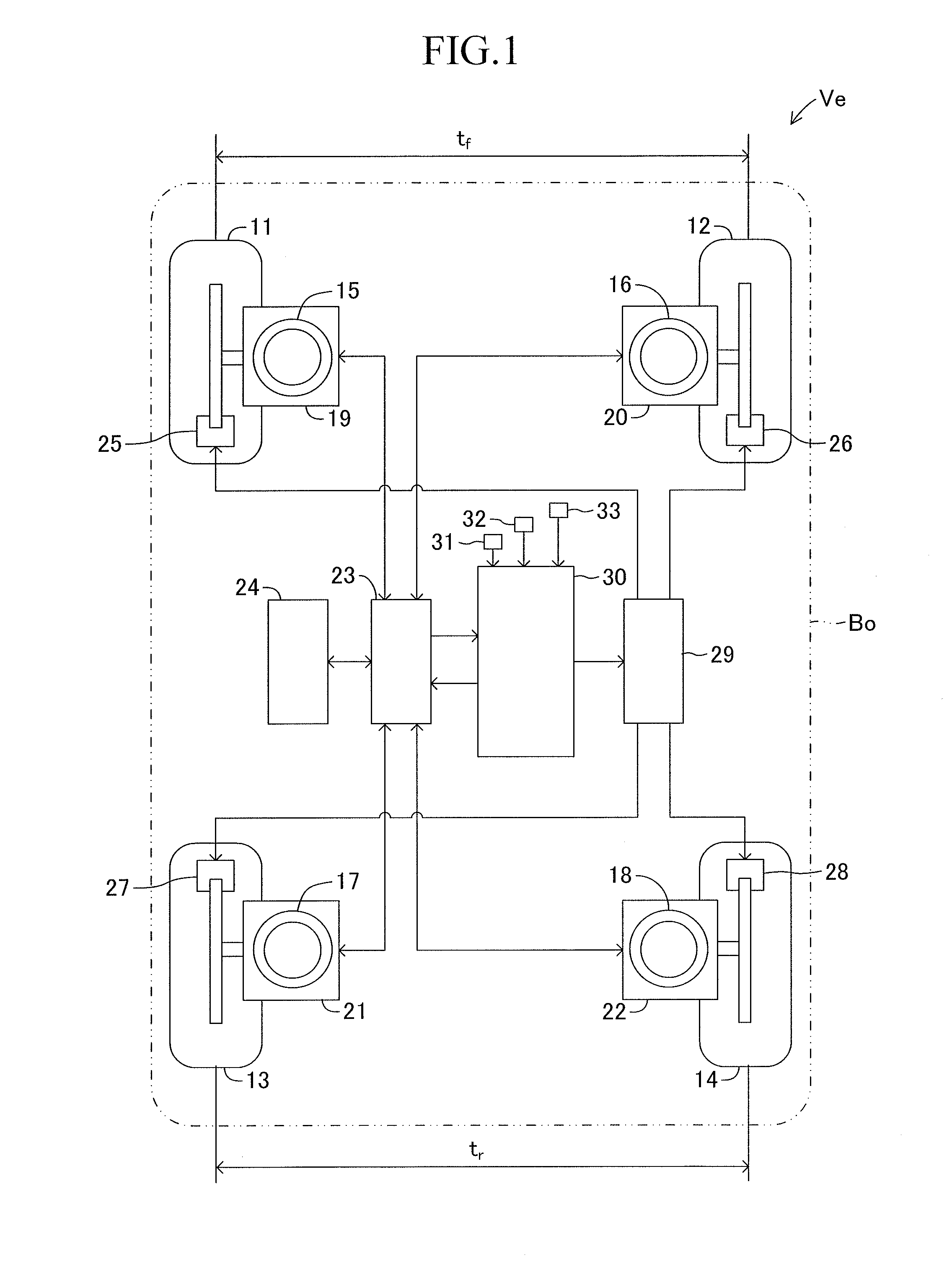
[0021]A detailed description is now given of an embodiment of the present invention referring to the drawings. FIG. 1 schematically illustrates a configuration of a vehicle Ve on which a vehicle braking / driving force control apparatus according to this embodiment is installed.

[0022]The vehicle Ve includes front left and right wheels 11 and 12 and rear left and right wheels 13 and 14. Then, the front left and right wheels 11 and 12 are mutually or independently supported via suspension mechanisms 15 and 16 by a body Bo serving as a sprung portion of the vehicle Ve. Moreover, the rear left and right wheels 13 and 14 are mutually or independently supported via suspension mechanisms 17 and 18 by the body Bo of the vehicle Ve.

[0023]On this occasion, configurations of the suspension mechanisms 15 to 18 do not directly relate to the present invention, and a detailed description thereof is therefore omitted. For example, a publicly known suspension such as a strut type suspension including ...


PUM


Abstract

Provided is a vehicle braking/driving force control apparatus for securing travel stability of a vehicle by priority when a slip occurs on a wheel for generating a braking/driving force while a plurality of motions are controlled. An electronic control unit identifies a slipping wheel having the maximum slip ratio (Si (i=fl, fr, rl, rr)) among wheels. The unit determines to increase or decrease a target roll moment (KmxMx) and a target pitch moment (KmyMy) for controlling a roll motion and a pitch motion, which are motions on the body in the vehicle vertical direction, so that the driving force on the slipping wheel has a direction to eliminate the slip state. The unit executes driving force distribution control so that a target longitudinal driving force (Fx) and a target yaw moment (Mz) for respectively controlling a longitudinal motion of a vehicle (Ve) and a yaw motion of a body (Bo), which are motions in vehicle longitudinal and lateral directions, and the increased/decreased moments (KmxMx, KmyMy) so as to simultaneous realize those factors.

Description

BACKGROUND OF THE INVENTION[0001]1. Field of the Invention[0002]The present invention relates to a vehicle braking / driving force control apparatus for individually controlling a braking force or a driving force to be generated on each wheel of a vehicle.[0003]2. Description of the Related Art[0004]In recent years, as a form of an electric vehicle, there has been developed a vehicle of so-called in-wheel motor type including a motor arranged inside or in a neighborhood of a wheel and using the motor to directly drive the wheel. On the vehicle of in-wheel motor type, a driving force and a braking force of the vehicle can be controlled as appropriate depending on a travel condition of the vehicle by independently controlling rotation of the motor provided to each wheel (driving wheel), in other words, independently controlling power running or regeneration of each motor. There has been proposed a control apparatus for controlling a motion (behavior) generated on a vehicle and a body wi...

Claims


Application Information

Patent Timeline
IPC IPC(8): B60W30/04B60W10/192B60W10/22B60W10/08
CPCB60W30/04B60W10/08B60W2030/043B60W10/22B60W10/192B60K7/0007B60L15/20B60W10/184B60W30/045B60W30/18172B60W2050/0024B60W2520/26B60W2710/083B60W2710/182B60W2720/14B60W2720/16B60W2720/18B60W2720/30B60L3/10B60L3/102B60L7/00B60L15/2009B60L2220/46Y02T10/64Y02T10/72
Inventor KATSUYAMA, ETSUO
Owner TOYOTA JIDOSHA KK
Why Eureka
Try Eureka