
Latching mechanism for a fuel tank isolation valve assembly

a technology of isolation valve and latching mechanism, which is applied in the direction of valve operating means/release devices, machines/engines, transportation items, etc., can solve the problems of reducing the overall efficiency of the vehicle, and achieve the effect of reducing electrical interference and reducing the electricity draw of the battery

Active Publication Date: 2015-04-16
VITESCO TECH USA LLC
View PDF1 Cites 15 Cited by
  • Summary
  • Abstract
  • Description
  • Claims
  • Application Information

AI Technical Summary

Benefits of technology

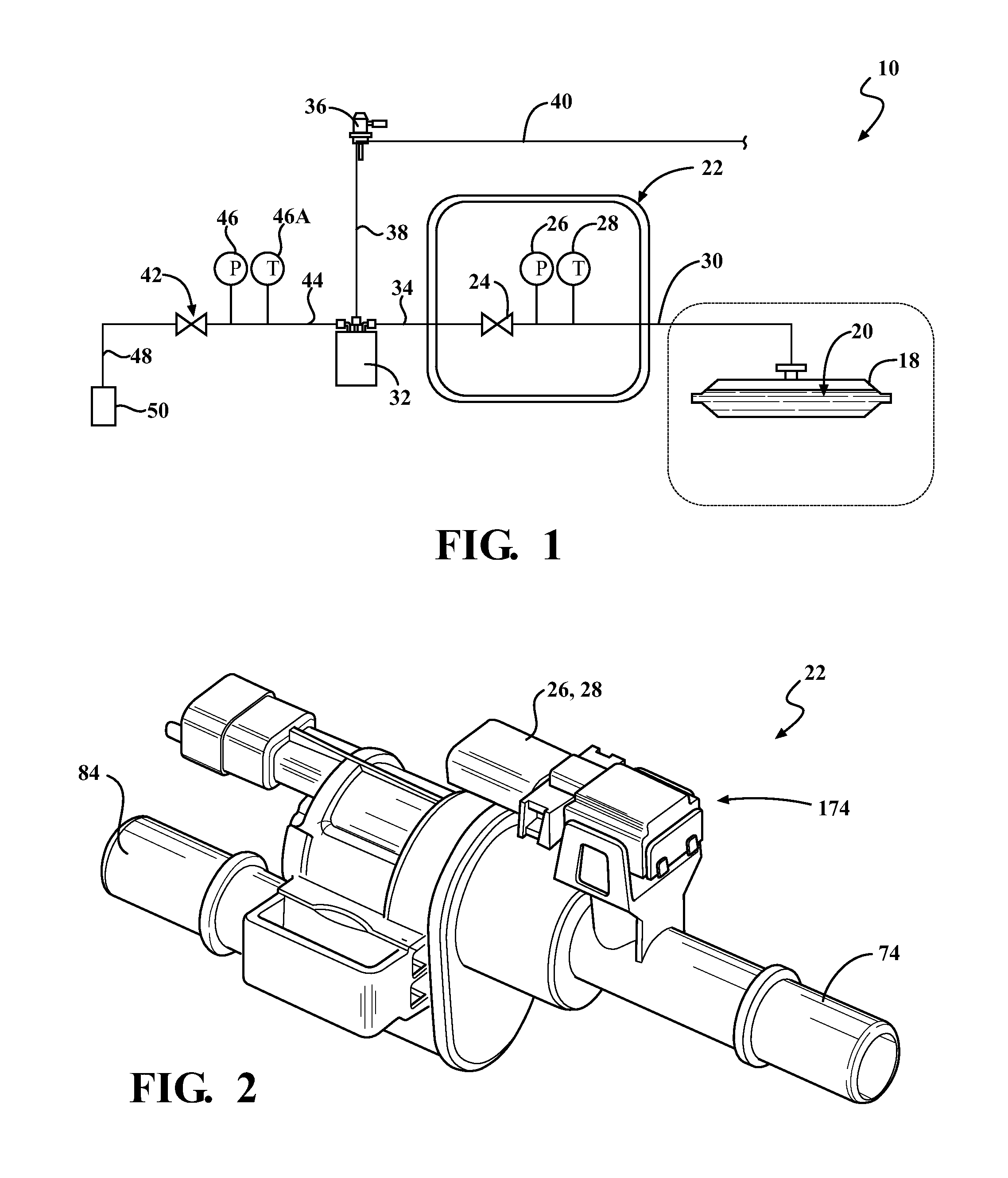
The present invention is an airflow system that includes a tank isolation valve and a canister vent valve, each with a latching mechanism to maintain the valve in an open position. This design reduces the electricity draw from the battery and prevents electrical interference with integrated pressure sensors. The system provides sealing for the fuel tank and canister, and a diagnostic test is performed using the tank isolation valve and the canister vent valve under different operating conditions. The tank isolation valve reduces power consumption from the battery while the valve is held in either an open or closed position. The valve uses a solenoid and a latching mechanism to avoid having to use continuous battery power. The valve design allows for efficient and reliable operation during refueling, reducing power consumption and electrical interference.

Problems solved by technology

This drains power from the battery, and reduces the overall efficiency of the vehicle.

Method used


Image

  • Latching mechanism for a fuel tank isolation valve assembly
  • Latching mechanism for a fuel tank isolation valve assembly
  • Latching mechanism for a fuel tank isolation valve assembly

Examples


Embodiment Construction

[0038]The following description of the preferred embodiment(s) is merely exemplary in nature and is in no way intended to limit the invention, its application, or uses.

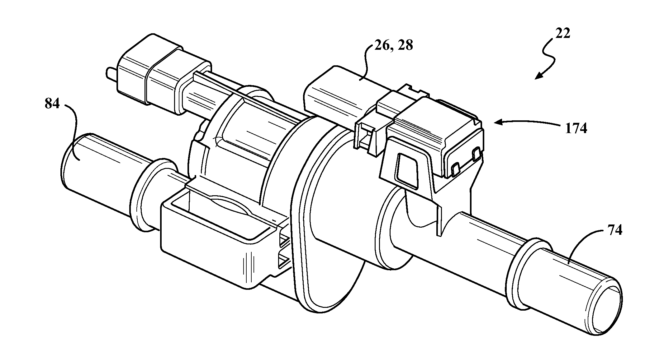
[0039]A diagram of a vapor purge system according to the present invention is shown in FIG. 1 generally at 10. The system 10 includes a fuel tank 18, where fuel 20 is stored. The fuel tank 18 is in fluid communication with an isolation valve assembly, shown generally at 22 in FIGS. 1-2. The isolation valve assembly 22 includes a tank isolation valve 24, a pressure sensor 26, and a temperature sensor 28. The valve 24 is in fluid communication with the fuel tank 18 through the use of a first conduit 30. Both the pressure sensor 26 and temperature sensor 28 are integrated with the isolation valve assembly 22, and are in fluid communication with the first conduit 30 in between the valve 24 and the fuel tank 18.

[0040]The tank isolation valve 24 is in fluid communication with a vapor canister 32 through the use of a second ...


PUM


Abstract

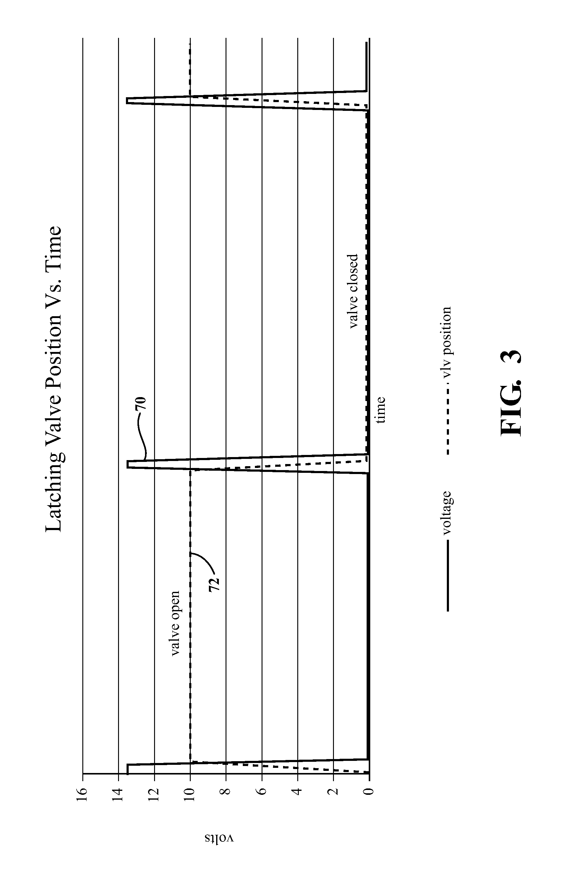
A vapor purge system having a tank isolation valve and a canister vent valve, where each valve includes a latching mechanism for maintaining the valves in an open position. A diagnostic test is performed on the purge system to prove that each of the valves are functioning correctly. Using latching valves in these applications reduces electricity draw from the battery and reduces electrical interference with integrated pressure sensors. The fuel tank is sealed by the tank isolation valve between the fuel tank and a vapor storage canister, and the canister vent valve provides sealing between the canister and the atmosphere, and controls venting of the canister. The tank isolation valve reduces power consumption from the battery, while the valve is being held in either an open position or a closed position by the latching mechanism, and uses only a single pulse of voltage to change the state of the valve.

Description

CROSS-REFERENCE TO RELATED APPLICATIONS[0001]This application claims the benefit of U.S. Provisional Application No. 61 / 891,018 filed Oct. 15, 2013. The disclosure of the above application is incorporated herein by reference.FIELD OF THE INVENTION[0002]The invention relates generally to a vapor purge system having a fuel tank isolation valve assembly integrated with a pressure sensor, as well as a canister vent valve, where the fuel tank isolation valve assembly includes a latching mechanism which maintains the fuel tank isolation valve assembly in an open position or closed position when no current is used.BACKGROUND OF THE INVENTION[0003]Current fuel systems for vehicles include a valve which opens and closes to allow vapor from the fuel tank to escape when the tank is being re-fueled. The vapor flows from the fuel tank, through the valve, and into a canister, where the vapor is stored until it is dispensed back into the intake of the engine. The valve is also able to provide reli...

Claims


Application Information

Patent Timeline
IPC IPC(8): F02M25/08F16K24/04
CPCF02M25/0836F16K24/04F02M2025/0845B60K2015/03576B60K2015/0358F02M25/089F16K31/0655F16K31/52408B60K15/03519
Inventor BALSDON, DAVID WILLIAMWOODS, BRIAN GORDON
Owner VITESCO TECH USA LLC
Learn More