Method and apparatus for controlling dust emissions with temperature control

a technology of temperature control and dust emission, which is applied in the direction of roads, roads, roads, etc., can solve the problems of generating dust in the milling chamber, mudding and fouling of ductwork, mudding and fouling of separation and filtering devices such as cartridge filters, cyclones,

Active Publication Date: 2015-04-16
ROADTEC
View PDF9 Cites 19 Cited by
  • Summary
  • Abstract
  • Description
  • Claims
  • Application Information

AI Technical Summary

Benefits of technology

[0024]The invention also comprises a method for operating such a working machine by conducting at least a portion of the heat from the engin

Problems solved by technology

During the operation of a milling machine or a road stabilizer/reclaimer machine, the surface pavement is broken by the cutter teeth of the milling drum, thereby generating dust in the mill

Method used


Image

  • Method and apparatus for controlling dust emissions with temperature control
  • Method and apparatus for controlling dust emissions with temperature control
  • Method and apparatus for controlling dust emissions with temperature control

Examples


Embodiment Construction

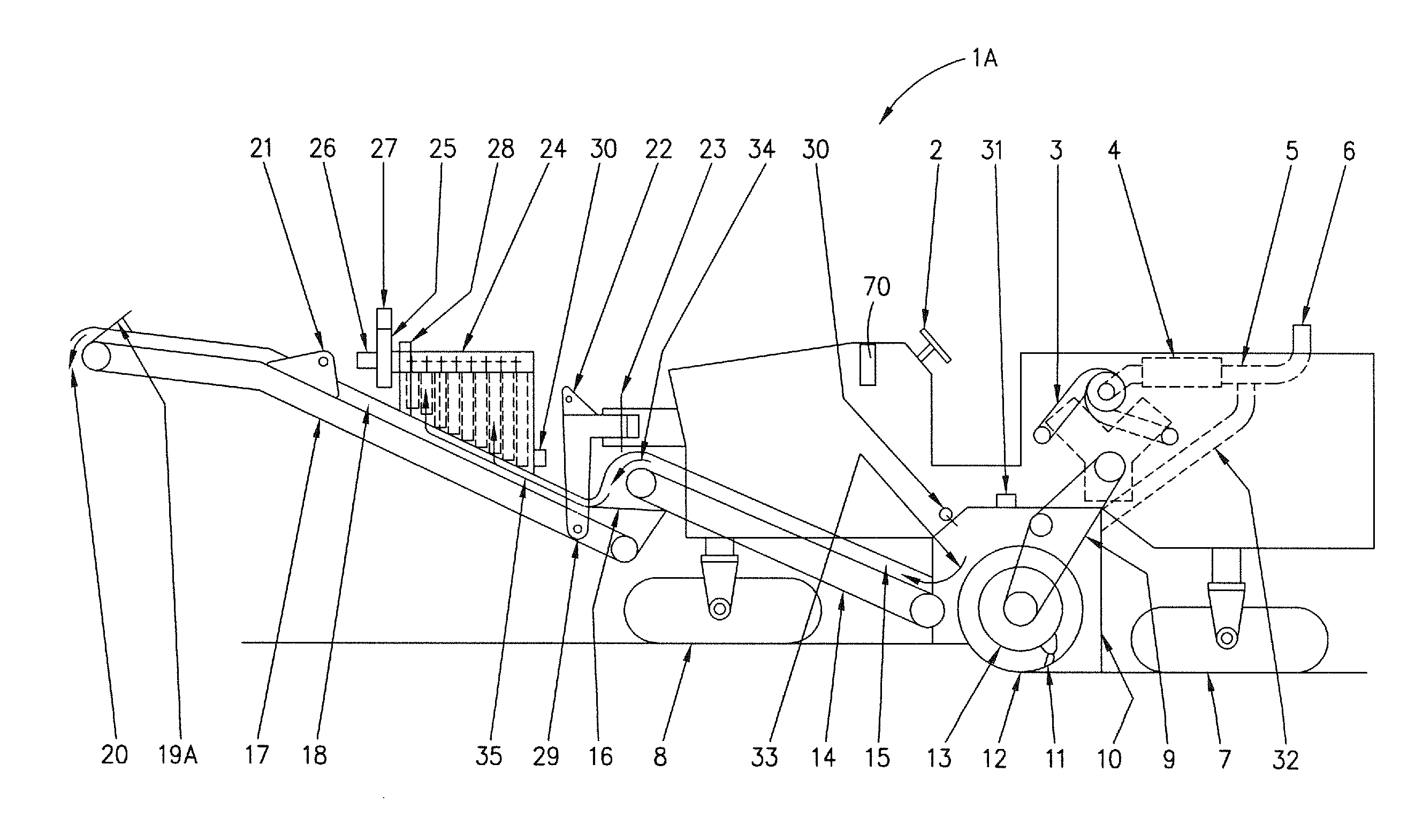
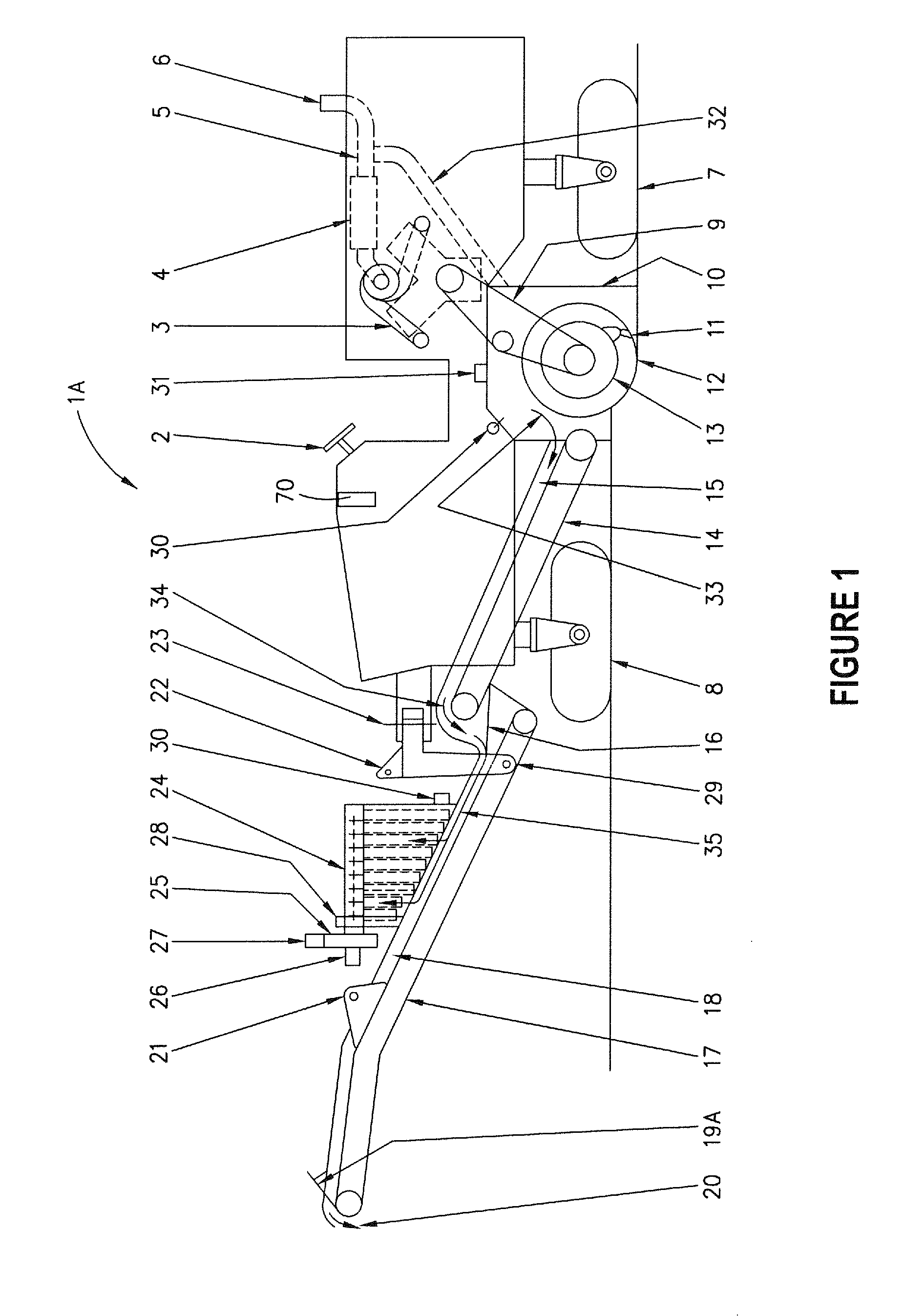
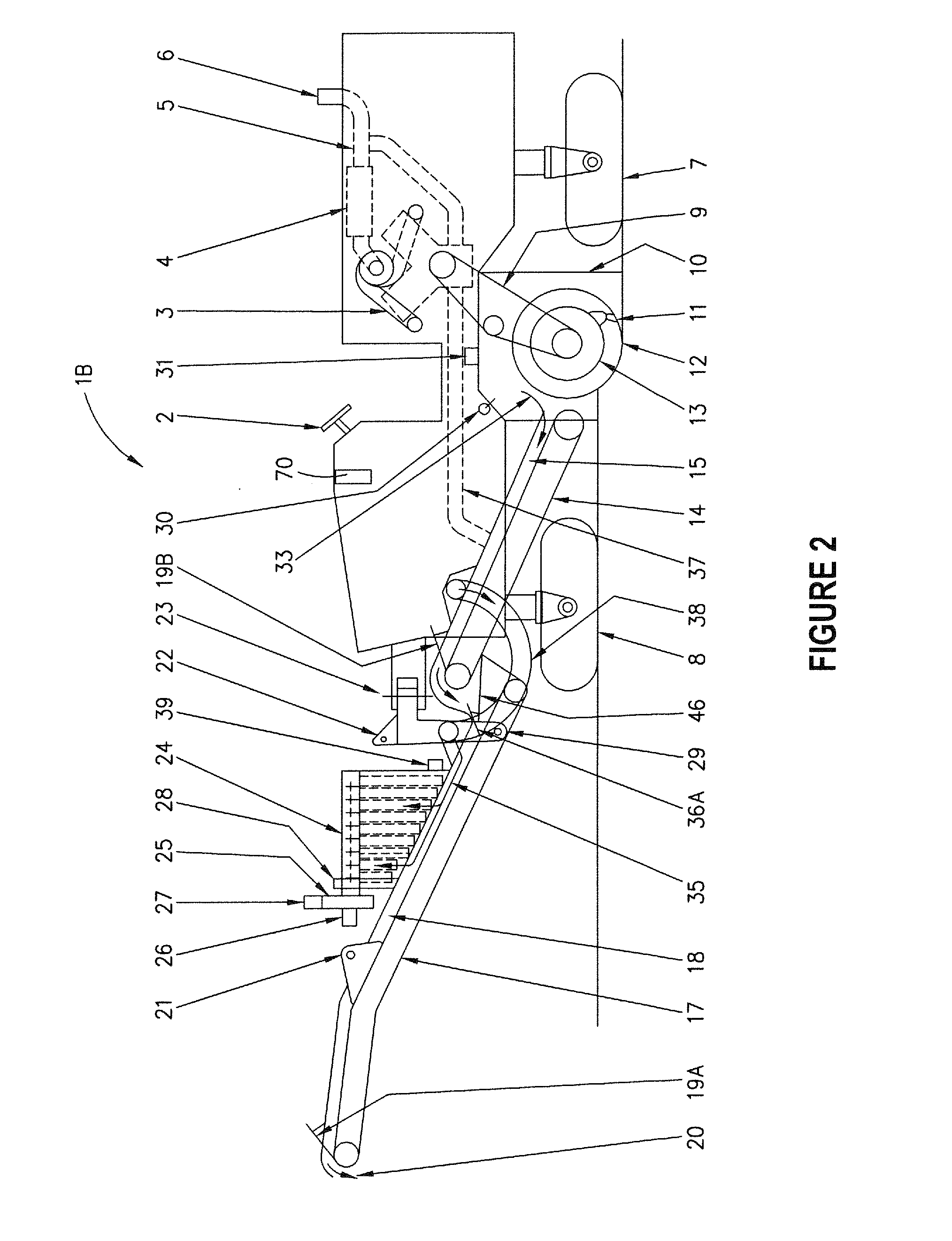
[0041]Milling machines 1A, 1B, 1C and 1D, all of which are similar, are illustrated in FIGS. 1-4, respectively. Each of these milling machines includes operator's station 2 and engine 3, typically a diesel engine. Operator's station 2 includes all of the controls necessary for driving and steering the milling machine, rotating milling drum 13, and controlling certain aspects of the invention, as explained hereinafter. Power from engine 3 is transmitted by drive belt 9 to milling drum 13, which is located in enclosed milling chamber 10. Milling drum 13 includes a plurality of cutter teeth 11 that are adapted to mill the road surface as the milling drum rotates and the machine is advanced along the roadway. The bottom 12 of the milling cut path coincides with the lower portion of the circular cutter tooth path inscribed by the plurality of cutter teeth 11 as milling drum 13 rotates.

[0042]Power from engine 3 is also transmitted by means known to those having ordinary skill in the art t...


PUM


Abstract

A working machine for use in milling the surface of a road includes a drive engine that produces engine exhaust gases. The working machine also includes a milling drum that is mounted for rotation against the surface of the road so as to generate milled material including dust from the road surface. The milling drum is contained within a milling chamber, and a spray assembly directs water into the milling chamber in such a manner that, during a period of rotation of the milling drum against the surface of the road, at least a portion of the water is converted to a vapor. A conduit is provided for conducting at least a portion of the engine exhaust gases into an enclosed space in communication with the milling chamber to raise the temperature of a gas stream therein containing vapor and dust from the milled material.

Description

CROSS-REFERENCE TO RELATED APPLICATION[0001]This application claims the benefit of U.S. Provisional Patent Application No. 61 / 891,635 which was filed on Oct. 16, 2013, and U.S. Provisional Patent Application No. 61 / 945,602 which was filed on Feb. 27, 2014.FIELD OF THE INVENTION[0002]This invention comprises a method and apparatus for raising the temperature of a gas stream that may contain water vapor and dust in a system, in a controlled manner, to a temperature at which mudding does not occur. The invention is useful for preventing ductwork mudding in systems without filtration devices and also in systems with filtration devices.BACKGROUND OF THE INVENTION[0003]A road milling machine includes a milling drum with a plurality of cutter teeth mounted thereon which is contained within a milling enclosure or chamber. The milling machine is adapted to be advanced across a road surface to “mill” the surface to remove asphaltic or Portland cement concrete road pavement in preparation for ...

Claims


Application Information

Patent Timeline
IPC IPC(8): E01C23/088
CPCE01C23/088E01C2301/50
Inventor MUSIL, JOSEPH E.
Owner ROADTEC
Why Eureka
Try Eureka