
Piezoelectric Damper System for an Axial Turbomachine Rotor

a technology of axial turbomachine rotor and damper system, which is applied in the direction of machines/engines, mechanical apparatus, liquid fuel engines, etc., can solve the problems of significantly reducing the fatigue life of the structure, heterogeneous flow, and ineffective damping method for strong amplitude vibrations

Active Publication Date: 2015-04-16
TECHSPACE AERO +1
View PDF3 Cites 10 Cited by
  • Summary
  • Abstract
  • Description
  • Claims
  • Application Information

AI Technical Summary

Benefits of technology

This patent describes a way to use piezoelectric transducers to damp vibrations on a rotating blade wheel. By arranging these transducers evenly over the wheel, and controlling their polarity, researchers have been able to combine capacitances and improve the resonance frequency of the system. This results in more efficient use of the piezoelectric transducers and better handling of lower frequencies.

Problems solved by technology

In fact, any body located in an axial homogeneous flow will generate variations of aerodynamic pressure in the surrounding environment thereof, thus making the flow heterogeneous.
Such vibratory levels are to be avoided since they are associated with high stress states, which significantly reduce the fatigue life of the structure and may lead to the destruction thereof.
However, this damping method is ineffective for a vibration of strong amplitude.
This system also involves providing each closed circuit with components, thus increasing mass and cost.
The necessary space for installing each circuit is disadvantageous.

Method used


Image

  • Piezoelectric Damper System for an Axial Turbomachine Rotor
  • Piezoelectric Damper System for an Axial Turbomachine Rotor
  • Piezoelectric Damper System for an Axial Turbomachine Rotor

Examples


Embodiment Construction

[0015]The present application aims to overcome at least one of the problems presented by the prior art. The present application improves the efficacy of a system for damping the vibration of a turbomachine rotor presenting modes with stationary or turning diameter(s). The present application also proposes a system for damping the vibration of a turbomachine rotor that can be just as effective at high frequency as at low frequency. The present application also reduces the weight of a system for damping the vibration of a turbomachine rotor.

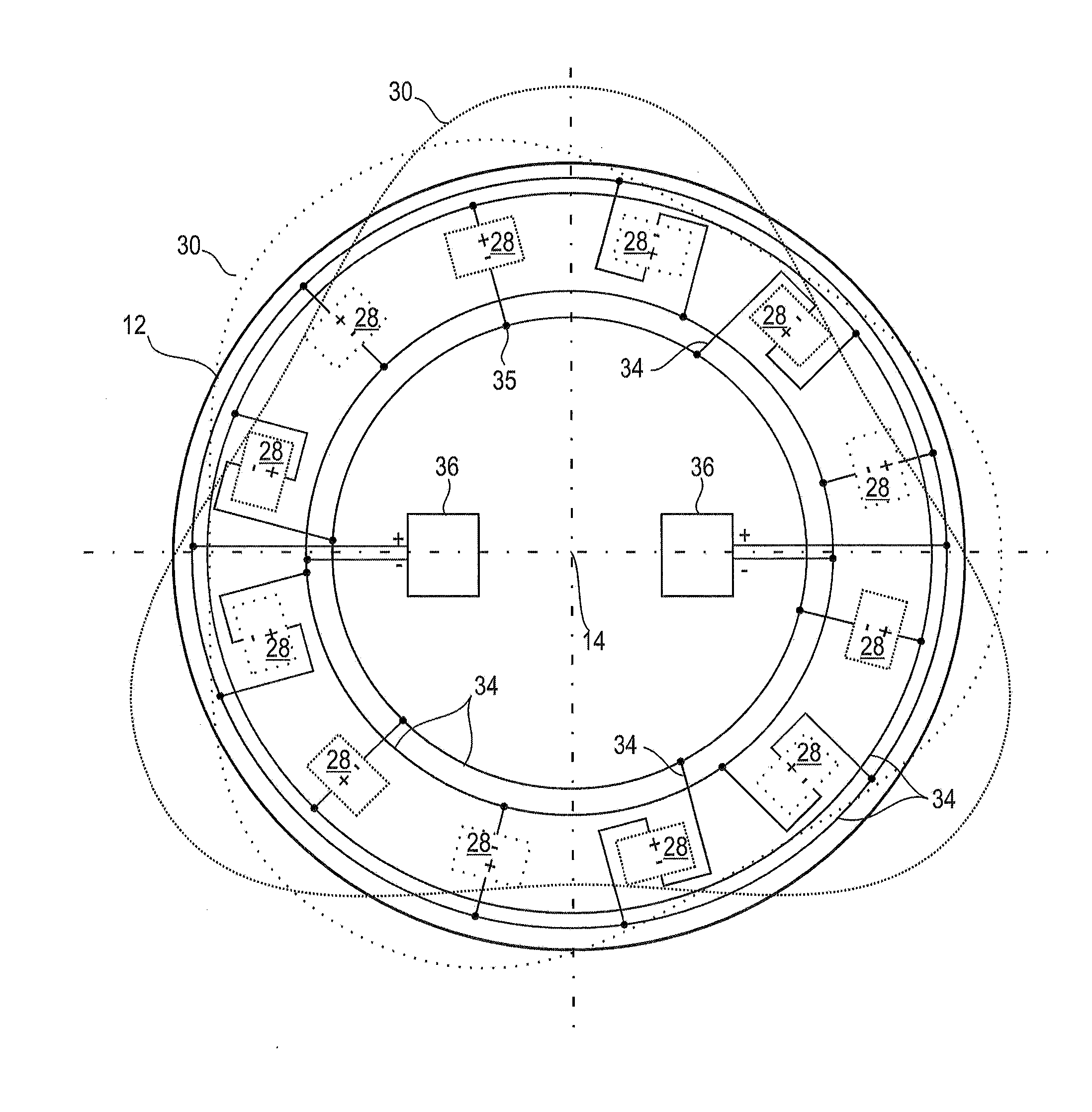
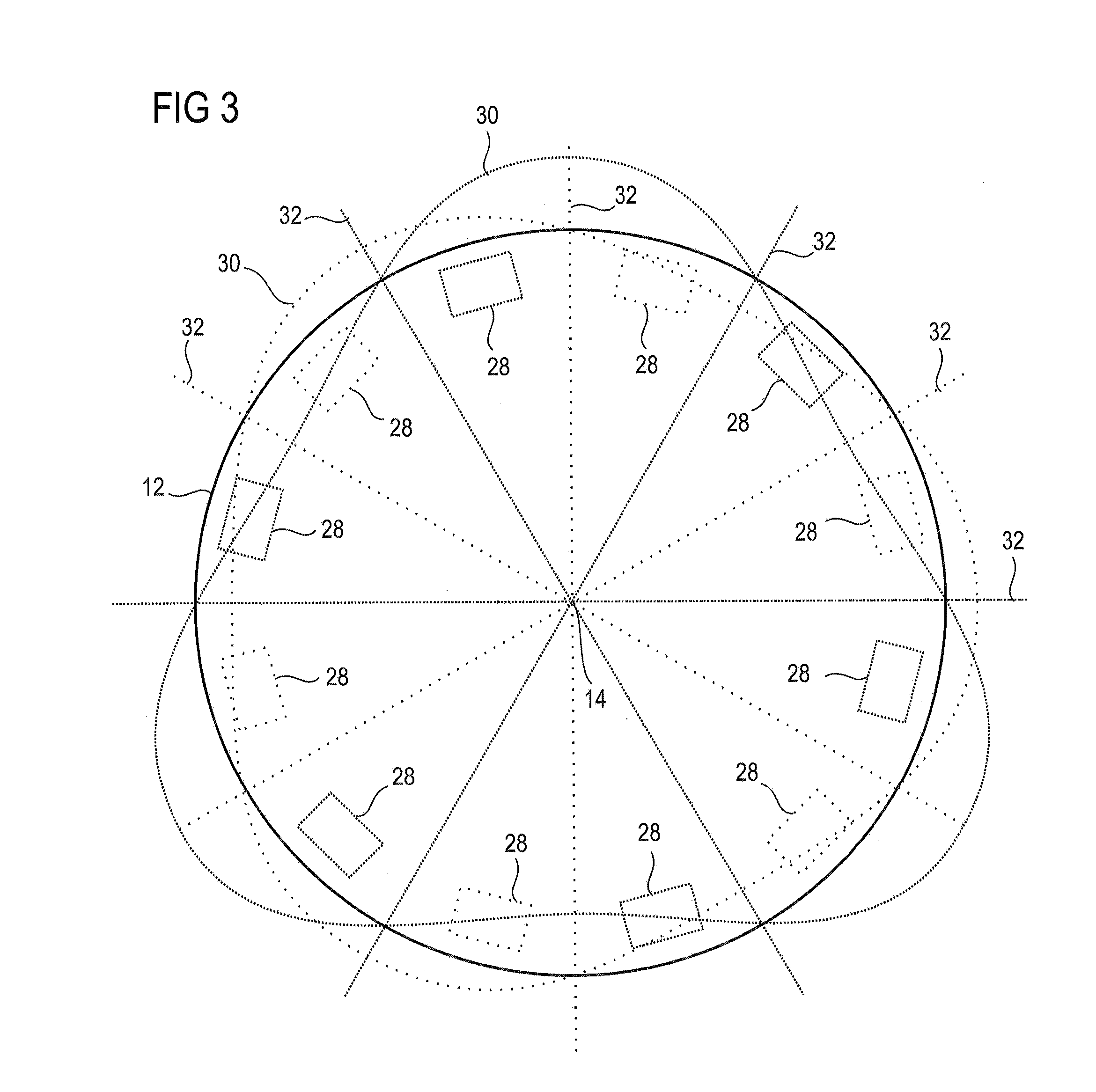
[0016]The present application relates to a rotor, in particular of a compressor, comprising a vibration-damping system which comprises at least one set of piezoelectric transducers distributed circularly over the rotor and connected to at least one dissipative circuit, a noteworthy feature being that the piezoelectric transducers are connected so as to pool the dissipative circuit or each of the dissipative circuits with a respective set of at leas...


PUM


Abstract

The present application relates to a rotor of a compressor or axial turbomachine comprising a vibration-damping system equipped with piezoelectric transducers distributed circularly and connected to dissipative resonant electric circuits. The circuits are closed and are equipped with a resistor and a coil. The piezoelectric transducers are divided into two sets of alternated transducers, each set being connected to a passive RLC circuit. In order to ensure a pooling of capacitances and currents thereof, the piezoelectric transducers are connected in parallel. During operation, the rotor is subjected to a turning excitation and is likely to vibrate and to deform in accordance with a modal shape with diameters with orthogonal deformation waves. The number of transducers is equal to the quadruple of the number of diameters of the mode, so as to be able to utilize the symmetrical character of this mode with diameters. The grouping of the piezoelectric transducers that deform in the same way makes it possible to damp the piezoelectric transducers with identical means thus pooled.

Description

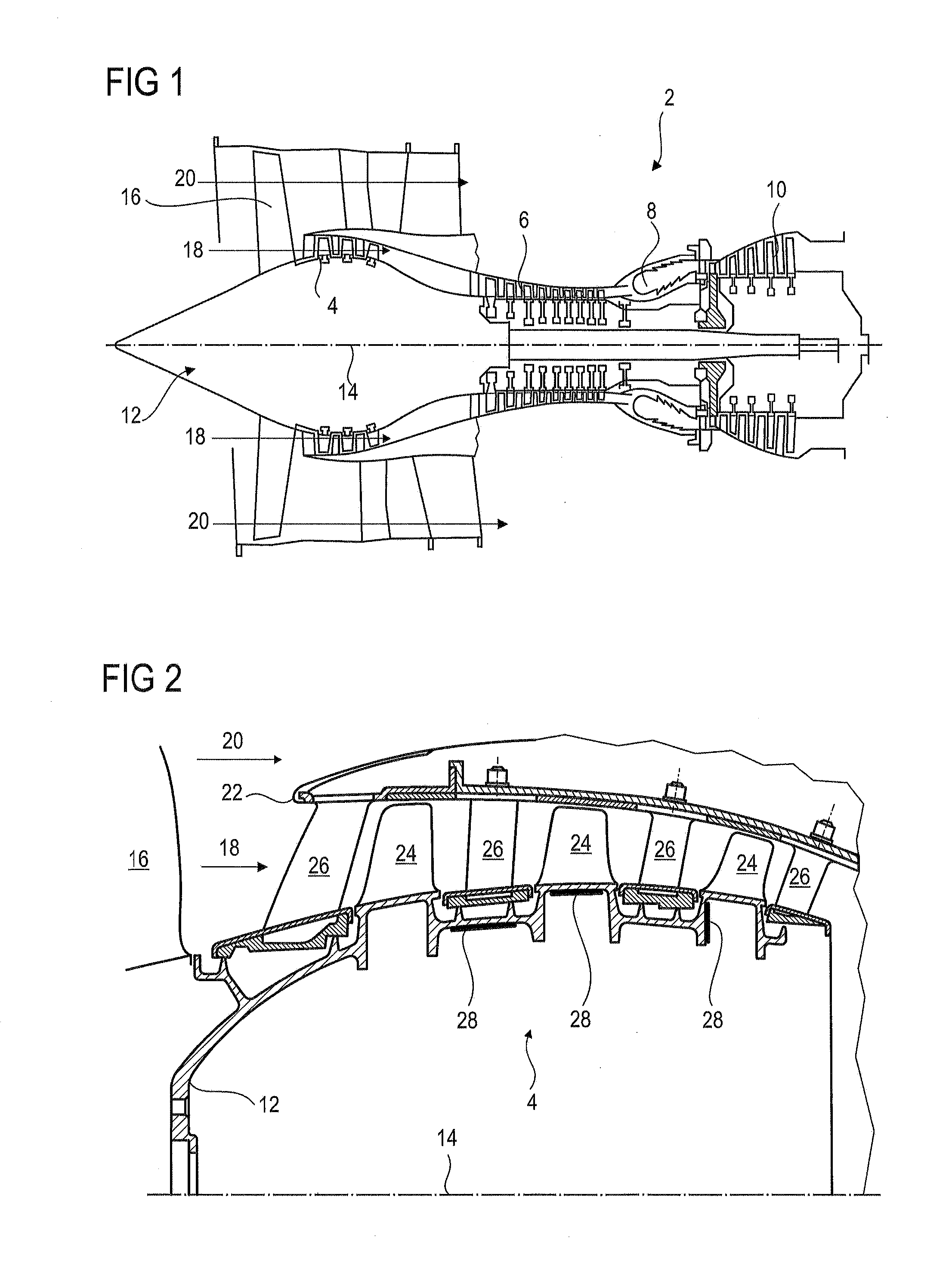
BACKGROUND[0001]1. Field of the Application[0002]The present application relates to an axial turbomachine rotor. More specifically, the present application relates to a system for damping vibrations of an axial turbomachine rotor. More specifically, the present application relates to a system for damping vibrations of bladed wheels of an axial turbomachine rotor with a dissipative electric circuit.[0003]2. Description of Related Art[0004]During operation, annular heterogeneous flows pass through an axial turbomachine. In fact, any body located in an axial homogeneous flow will generate variations of aerodynamic pressure in the surrounding environment thereof, thus making the flow heterogeneous. These bodies may be, inter alia, blades, case struts, or variable discharge gates.[0005]When a blade of a bladed rotor turns in an annular flow having such circumferential heterogeneities, each sudden variation of pressure will be considered as a punctiform excitation. The number of excitatio...

Claims


Application Information

Patent Timeline
Patent Type & Authority Applications(United States)
IPC IPC(8): F04D29/66H01L41/113H10N30/30
CPCF04D29/668H01L41/113F05D2260/96F01D5/10F16F15/005F04D29/666F01D25/04F01D5/06F05D2220/323F05D2220/3216F05D2270/334F05D2270/114F05D2270/62F16F15/10H10N30/30
Inventor VIGUIE, REGISVERHELST, DAMIENPREUMONT, ANDREMOKRANI, BILALBASTAITS, RENAUD
Owner TECHSPACE AERO
Learn More