Therapeutic energy systems

a technology of energy systems and energy sources, applied in the field of therapeutic devices, can solve the problems of significant cost associated with purchasing, storing and maintaining a dedicated console for each of a large variety of operational heads, and the system described by shah et al. is limited to the type and mode of the prob

Inactive Publication Date: 2015-04-16
RBC DEV LLC
View PDF7 Cites 85 Cited by
  • Summary
  • Abstract
  • Description
  • Claims
  • Application Information

AI Technical Summary

Benefits of technology

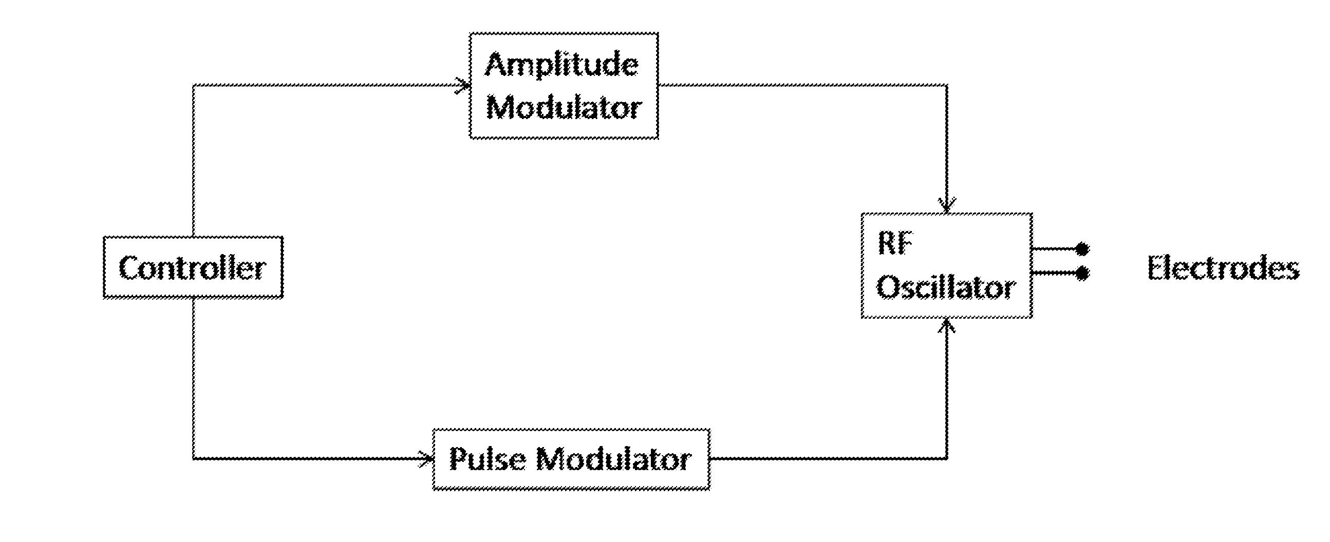
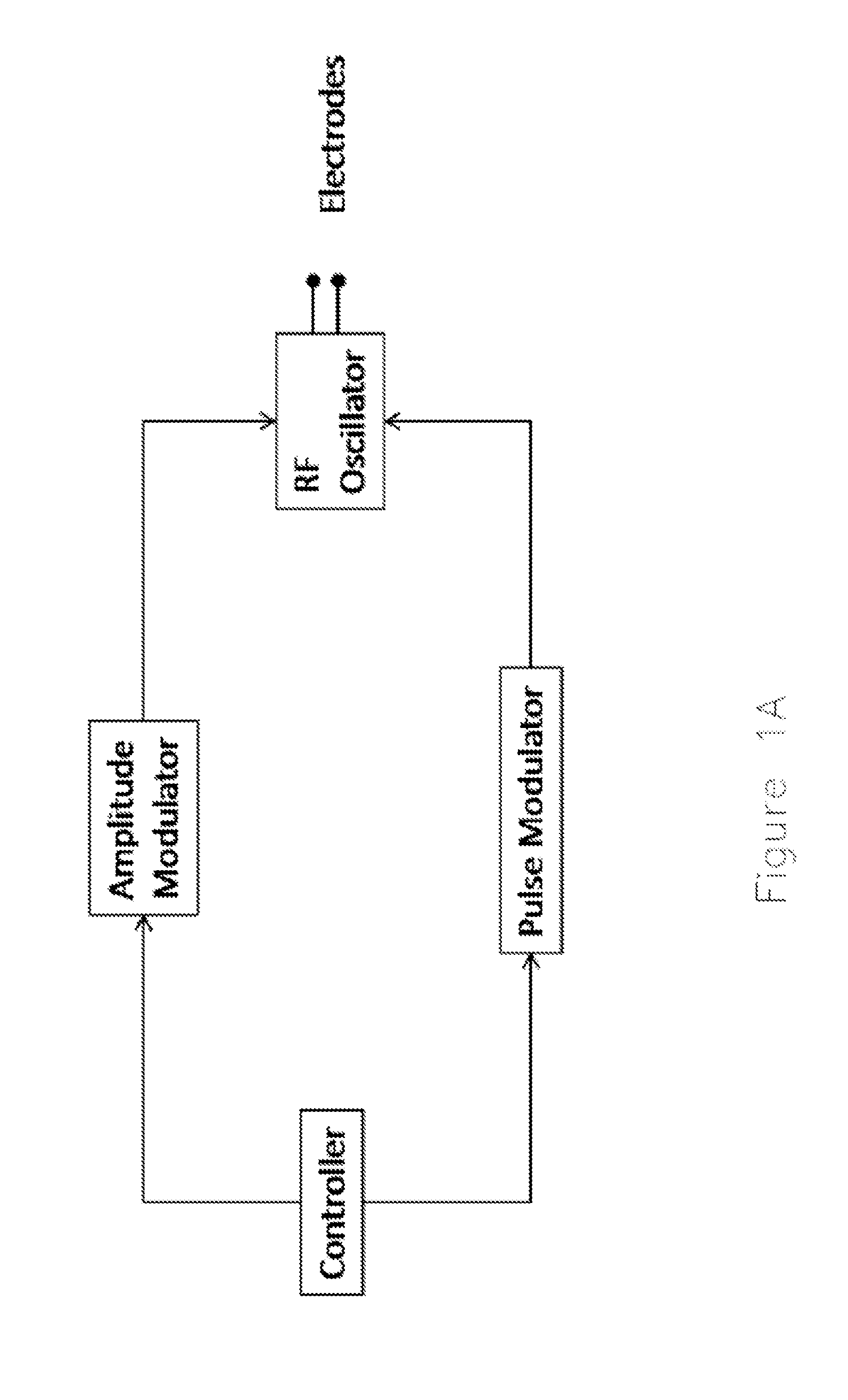
[0016]Optionally, the energy generator is an RF generator or other electromagnetic energy generator and the control instructions comprise one or more parameters of RF output or other energy output. Optionally, the one or more parameters of RF output or other energy output comprise one or more of: voltage, current, temperature, stimulation rate, pulse rate, pulse duration, ramp time, frequency, waveshape, and power.
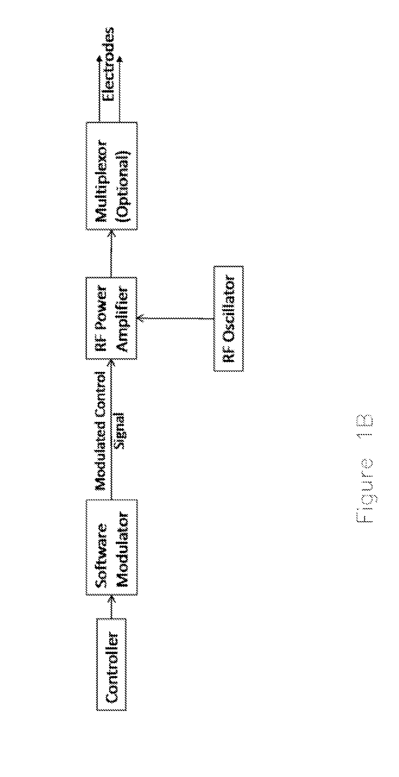
[0017]Optionally, the system further comprises one or more sensors. Optionally, the reversible connector is configured for operably linking the one or more sensors to the controller. Optionally, the one or more sensors are configured for sensing or monitoring (‘monitoring’) one or more parameters. Optionally, the one or more parameters are selected from: an energy (e.g. RF) output parameter, an environmental condition, a biological condition), a therapeutic device condition (e.g. user input condition such as button, indicator, lever, or switch status). Optionally, the control instructions comprise instructions for controlling the sensor and / or for controlling the RF output (e.g. modulating RF output differentially) based on the monitored one or more parameters.
[0018]Optionally, the therapeutic device comprises an energy delivery head and at least one additional therapeutic head. Optionally, the control instructions further comprise instructions for controlling the at least one additional therapeutic head. Optionally, the at least one additional therapeutic heads are selected from: an irrigation head (e.g. cannula or lumen for connection to a fluid pump), an aspiration head (e.g. cannula or lumen for connection to a fluid pump), a lighting head, an expandable device, a cutting head, and one or more RF heads.
[0019]Optionally, the control instructions comprise one or more parameter values or one or more algorithms, e.g. for conducting a therapeutic procedure or otherwise controlling connected devices or providing instruction.
[0020]Optionally, the control instructions comprise one or more parameters selected from energy output parameters, UI output parameters, calibration parameters, verification parameters, capability parameters, and input parameters.

Problems solved by technology

A limitation of conventional RF devices is that each console is typically configured for only a limited number of operational heads.
Consequently, there is a significant cost associated with purchasing, storing and maintaining a dedicated console for each of a large variety of operational heads.
Accordingly, the system described by Shah et al. is limited to probe types and modes pre-configured into the generator.
Shah et al. do not teach storing the operating modes or control instructions on the probe.
Eubanks et al. fail to teach a catheter assembly comprising memory instructions for controlling user interface of a console.
Further, Eubanks et al. fail to teach a catheter assembly comprising memory instructions for controlling RF output of a reversibly connected RF generator.

Method used


Image

  • Therapeutic energy systems
  • Therapeutic energy systems
  • Therapeutic energy systems

Examples


example 1

Therapeutic System

[0441]FIG. 5 depicts one embodiment of the present invention. The system comprises[0442]a. a console comprising an RF generator and a controller configured for controlling the RF output of the RF generator;[0443]b. a therapeutic device comprising:[0444]i. an operational head configured for receiving the RF output and delivering RF energy to the biological tissue; and[0445]ii. a memory device comprising control instructions for said controlling the RF output; and[0446]c. a reversible connector configured for operably linking:[0447]i. the RF generator to the operational head; and[0448]ii. the memory device to the controller.

[0449]The connector on the console side comprises a jack. The connector on the therapeutic device side comprises a plug configured for the jack.

[0450]The operational head comprises an RF ablation head comprising a pair of electrodes configured in monopolar or bipolar mode. The operational head is configured as, e.g. a handpiece comprising an RF ab...

example 2

Therapeutic System

[0457]A system of the invention (e.g. as detailed in Example 1) is provided, wherein the control instructions contain the specifications of energy parameters (e.g. power, voltage, waveshape, duty cycle, frequency, pulse frequency, pulse duration, impedance targets, and power adjustments to apply in response to impedance changes) for the RF energy to be applied to the treatment site to cut or ablate physiological structures.

[0458]The power delivered by the energy generator is optionally specified to vary based on detection of rapid impedance changes, such as could be the case when localized boiling or ‘popping’ occurs. The control instructions optionally further specify impedance readings or trends which provide indications of proper or improper contact of electrodes to physiological structures. The control instructions optionally contain information as to how this information is to be displayed by the generator, containing characteristics such as text size, graph a...

example 3

Therapeutic System

[0459]The system detailed in Example 2 is optionally further provided with one or more temperature sensors configured detect the changes in temperature of the electrode(s). The sensory input of the temperature sensors is used to limit the duration of treatment, alter the energy applied, or otherwise inform the operator of said temperatures. This function is provided by parameters in the memory device, e.g. minimum and maximum temperature limits, limits based on the rate of change of temperature, amount of alteration the energy delivery based on the temperature response observed at the electrodes, allowable ranges of thermal impedance (e.g. change in temperature as it relates to the rate or total quantity of energy delivered, or temperature response when energy is increased, reduced, or removed).


PUM


Abstract

The invention provides a therapeutic system comprising:
    • a console, wherein the console comprises a controller and an energy generator;
    • a therapeutic device comprising: an operational head configured for transmitting the energy output from to a biological tissue; and a memory device comprising control instructions, wherein said control instructions comprise instructions for controlling the console;
    • a reversible memory operable linkage linking the memory device to the controller; and
    • a reversible connector configured for operably linking the energy generator to the operational head.
Optionally, the energy generator is a generator of ablation energy or heat energy (e.g. RF generator) and the control instructions comprise instructions for controlling the output of the energy generator. Optionally, the control instructions comprise one or more parameters of energy output or an algorithm configured for controlling the energy output. Optionally, the system further comprises one or more secondary therapeutic devices and the control instructions comprise instructions for controlling the one or more secondary therapeutic devices. Optionally, the system further comprises one or more sensors configured for sensing parameters of energy output or biological or environmental effects of the energy output and the control instructions comprise instructions for controlling the energy output and/or secondary therapeutic devices based on the parameters of energy output or biological or environmental effects. In some embodiments, one advantage provided by the present invention is the use of a single console with a plurality of interchangeable reversibly connected therapeutic devices.

Description

RELATED APPLICATIONS[0001]This application is a continuation of International Application PCT / US2013 / 056072 filed 22 Aug. 2013 which claims the priority of U.S. Provisional Patent Application Ser. No. 61 / 692,228 filed on 22 Aug. 2012, the contents of each of which are incorporated herein by reference in its entirety.TECHNICAL FIELD[0002]The present invention relates to therapeutic devices.BACKGROUND[0003]The delivery of radio frequency (‘RF’) energy to target biological tissue is known for a variety of purposes. In one particular application, RF energy is delivered for ablating the target tissue.[0004]Conventional RF devices comprise a console (RF generator and controller) and a removable operational head (e.g. RF probe or RF catheter) configured for contacting the target tissue. A limitation of conventional RF devices is that each console is typically configured for only a limited number of operational heads. For example, at the time of purchasing new operational heads for a new te...

Claims


Application Information

Patent Timeline
Patent Type & Authority Applications(United States)
IPC IPC(8): A61N7/02A61B18/12A61M5/142A61B18/14A61N5/02A61M5/172A61N5/06A61B18/02A61N1/44A61B17/32A61M1/00A61M3/02G05F1/66A61N7/00
CPCA61N7/02G05F1/66A61B18/1206A61M5/142A61B18/1477A61N5/025A61N7/00A61N5/06A61B18/02A61N1/44A61B17/32A61M1/008A61M3/02A61M5/1723A61B2018/00648A61B2018/143A61B2018/0022A61B2018/00267A61B2018/00577A61B2018/00613A61B2018/00595A61B2018/00601A61N2005/067A61M11/00A61B2017/00482A61M16/06A61M16/0816A61M16/0875A61M16/14A61M16/16A61M2016/0027A61M2205/3569A61M2205/3592A61M2205/502A61M2205/52A61M2205/6018A61M2205/70A61B18/14A61B2018/00702A61B2018/00821A61B2018/00839A61B2018/00863A61B2018/0016A61B2018/00178A61B2018/00988A61M2230/60
Inventor MAYER, CARLELLENZ, JOHN
Owner RBC DEV LLC
Why Eureka
Try Eureka