Throat Microphone

Inactive Publication Date: 2015-04-23
AUDIO-TECHNICA
View PDF5 Cites 1 Cited by
  • Summary
  • Abstract
  • Description
  • Claims
  • Application Information

AI Technical Summary

Benefits of technology

[0013]According to the present invention, the piezoelectric device vibrates parallel to a surface of the base. This can reduce the distance between the vibrating surface of the piezoelectric device and the surface of the bas

Problems solved by technology

Unfortunately, the sealant 66 covering the overall vibration system in FIGS. 3 and 4 cannot readily re

Method used


Image

  • Throat Microphone
  • Throat Microphone
  • Throat Microphone

Examples


Example

[0018]Embodiments of a throat microphone of the present invention will now be described with reference to the attached drawings.

Embodiments

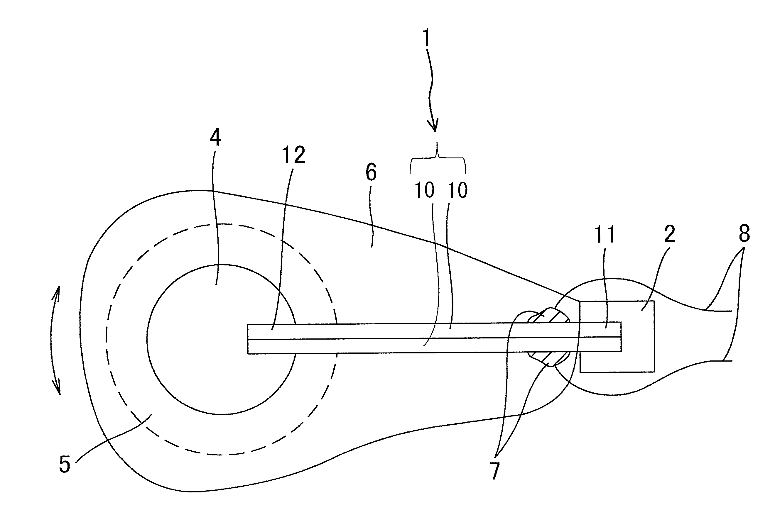
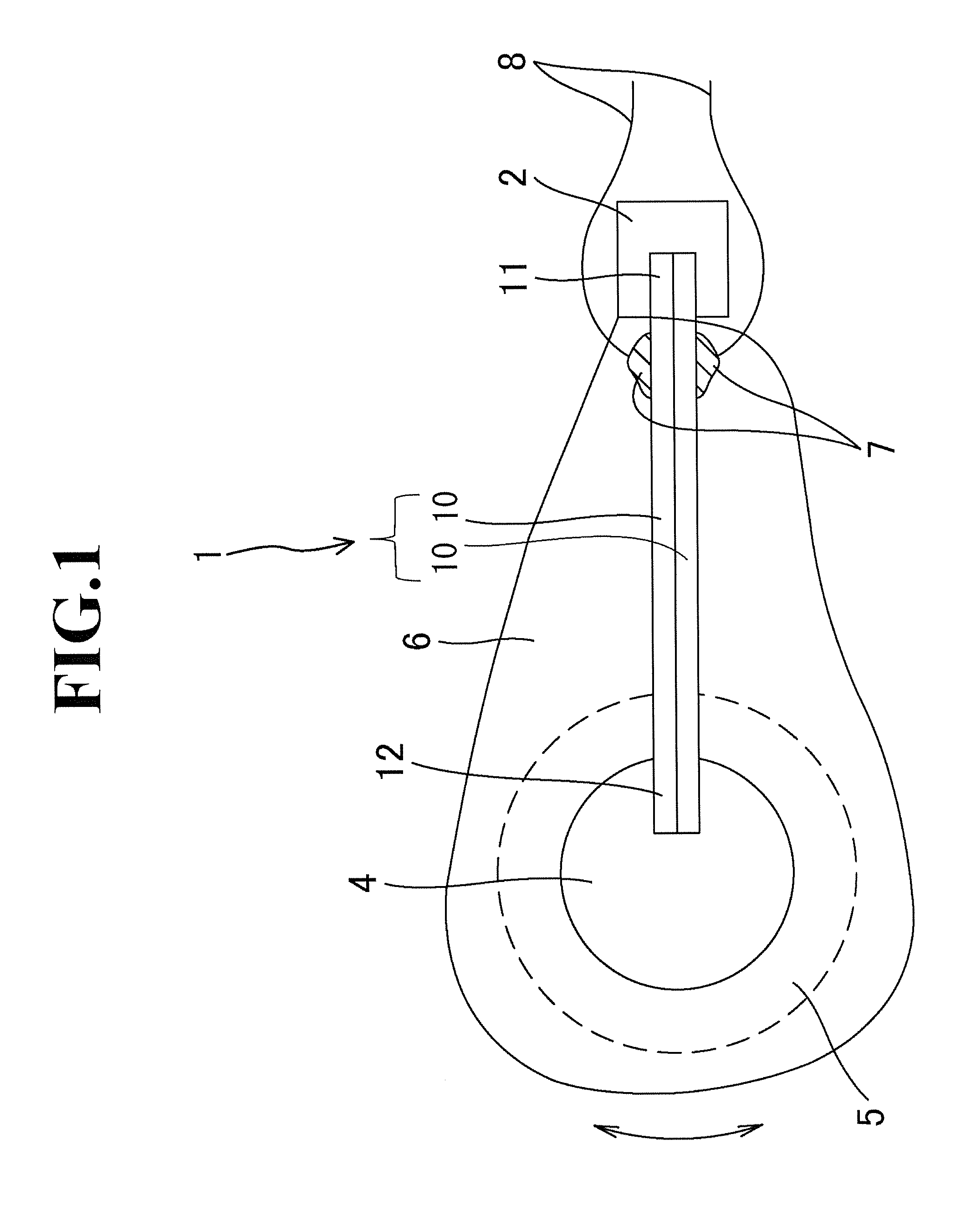
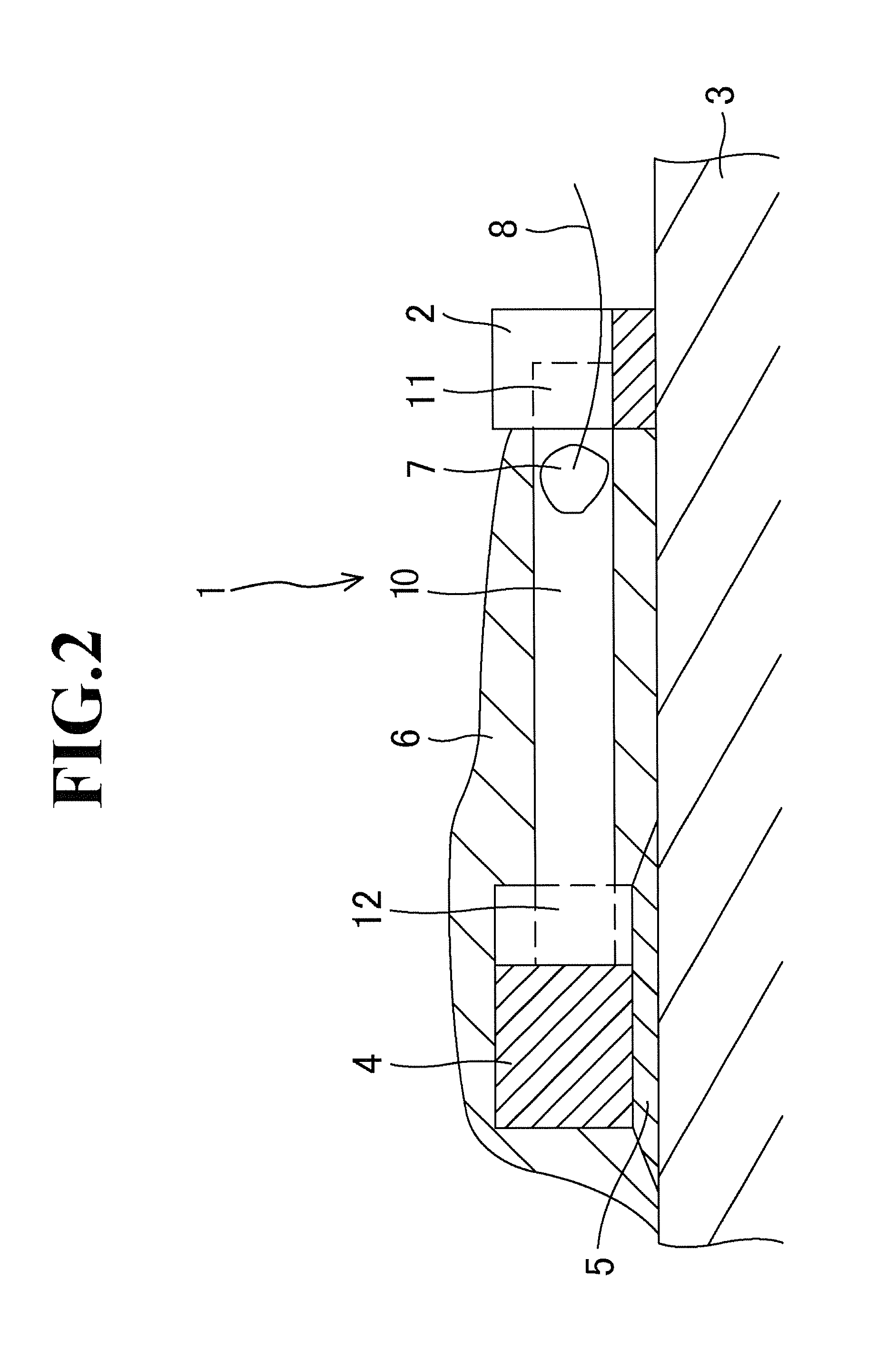
[0019]FIGS. 1 and 2 illustrate a piezoelectric device 1 that is a piezoelectric bimorph consisting of two plate piezoelectric elements 10 bonded to each other. The output of the piezoelectric device 1 is the sum of signals from these two piezoelectric elements 10. The piezoelectric device 1 has a fixed end 11. The fixed end 11 is embedded to a stationary member 2 integrated with a base 3. Thus, the fixed end 11 of the piezoelectric device 1 is substantially fixed or integrated with the base 3, so that the piezoelectric device 1 is cantilevered.

[0020]The piezoelectric device 1 extends from the stationary member 2 parallel to a surface of the base 3, with a predetermined distance from the base 3. The piezoelectric device 1, which is resilient, can vibrate with the end 11 as a support in response to vibrations applied thereto. The end 11 is fixed to...


PUM


Abstract

A throat microphone includes a cantilevered piezoelectric device 1 having a fixed end 11 supported by a base 3 and a free end with an anchor 4 fixed thereto. The piezoelectric device 1 vibrates to output audio signals in response to vibrations of a throat. The fixed end is attached to the base 3 such that the piezoelectric device 1 vibrates parallel to the surface of the base 3. A gap is defined between the anchor 4 and the base 3. The gap is provided with a vibration absorber 5.

Description

TECHNICAL FIELD[0001]The present invention relates to a throat microphone including a cantilevered piezoelectric device for converting vibrations of a throat into audio signals.BACKGROUND ART[0002]Throat microphones, which convert vibrations of throats into audio signals, have an advantage in that they can precisely convert human voices into audio signals even in noisy environments. A typical throat microphone includes an acoustoelectric transducer consisting of a piezoelectric device. Such a transducer of the throat microphone generally includes a compact piezoelectric bimorph that can output high levels of signals in response to displacement.[0003]FIGS. 3 and 4 illustrate a technology on a throat microphone including a piezoelectric bimorph. In the drawings, a piezoelectric device 50 consisting of a piezoelectric bimorph has a fixed end 51. The fixed end 51 is embedded in a stationary part 62 that protrudes from a base 63. The piezoelectric device 50 is cantilevered in such a mann...

Claims


Application Information

Patent Timeline
IPC IPC(8): H04R1/46H04R17/02H04R1/42
CPCH04R1/46H04R17/02H04R1/42H04R1/14H04R7/26H04R17/00
Inventor AKINO, HIROSHI
Owner AUDIO-TECHNICA
Why Eureka
Try Eureka