

Methods of Using Near Field Optical Forces
a near field and optical force technology, applied in the direction of lasers, microscopes, masers, etc., can solve the problem that the analysis is often hampered by the motion of substances
- Summary
- Abstract
- Description
- Claims
- Application Information
AI Technical Summary
Benefits of technology
Problems solved by technology
Method used
Image

Examples
example 1
Multi-Chamber Particle Characterization
[0120]Production of pharmaceutical preparations often contains undesired contaminants within starting materials, intermediates, and / or final preparations. Presence of such contaminants can influence the overall effectiveness and safety of the product. While certain techniques may be able to provide information regarding particle contaminants greater than 2 μm in diameter, standard techniques are limited in interrogating the presence and / or properties of smaller contaminants.
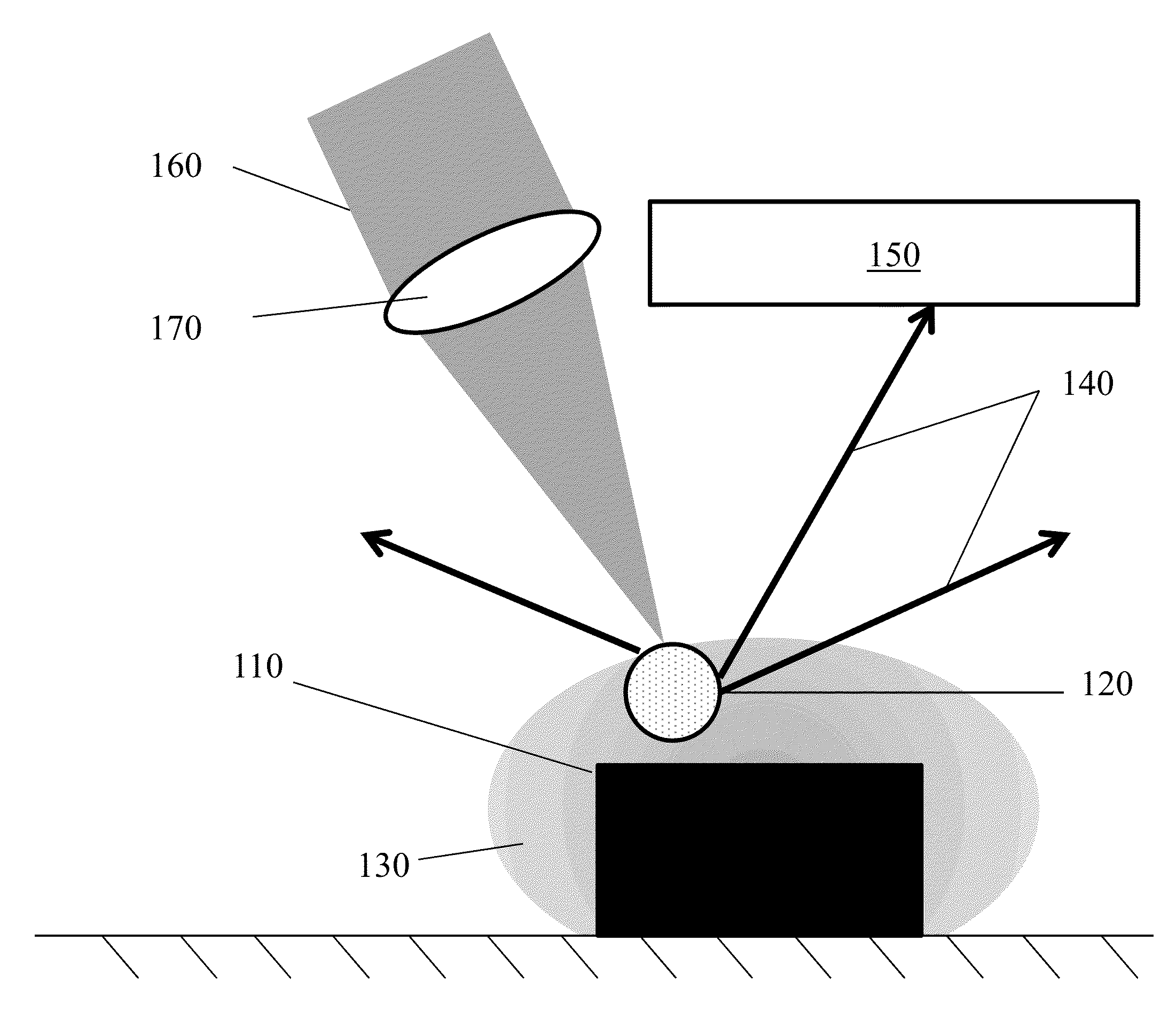
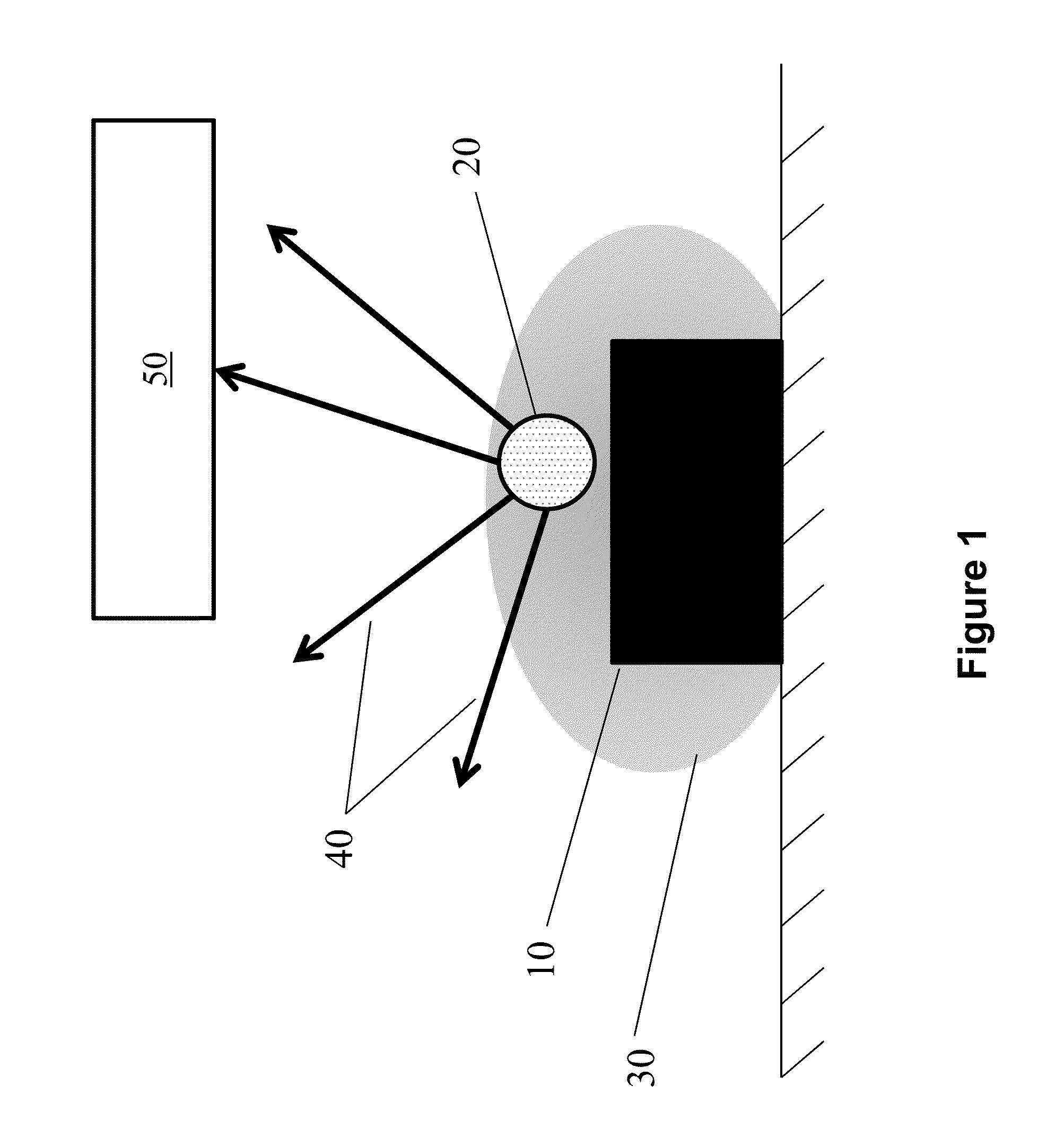
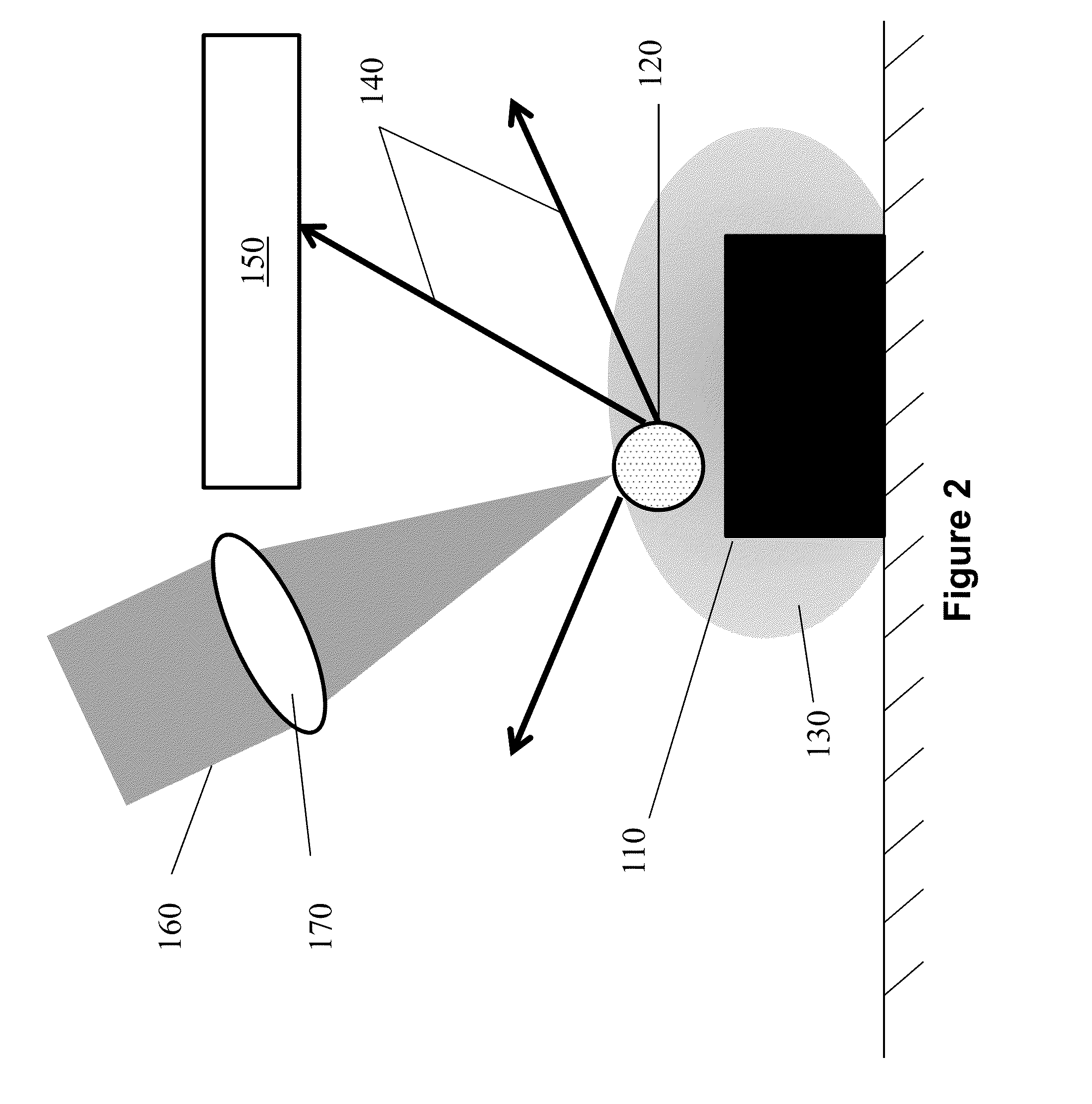
[0121]As described herein, optical traps can be used in methods and systems to determine (1) how many particles there are in the solution, (2) what sizes these particles are and (3) what these particles composed of (e.g. rubber, protein, steel, oil)?
[0122]To investigate the presence and properties of small contaminants within a final pharmaceutical product, a fluid sample of the product is loaded into a chamber that contains a waveguide-based optical trap. This waveguide is ...
example 2
Binding kinetics
[0137]The binding kinetics of a trapped substance is measured. Using a near-field optical trap within a channel, the binding rate of a fluorescently labeled small molecule (B) to a protein (A) is measured. The channel and materials are passivated by flowing in a blocking buffer (such as Bovine Serum Albumin). The trap is then activated. A protein is applied (i.e. by flowing the protein into the channel) and the protein is captured by the trap. The unbound protein is washed away with an appropriate buffer. Molecule B is flowed into the trap at a controlled rate. While molecule B is flowing in, the fluorescence of the trap is measured, thereby by providing the binding rate of B to protein A. Unbound B can also be washed away. Another fluorescent measurement of the trap is made to determine the affinity of molecule B to protein A. The protein bound to or not bound to molecule B is optionally eluted and analyzed.
example 3
Dissociation of Aggregates / Complexes
[0138]Using a near-field optical trap within a channel, testing the concentration of chemical B to disassociate fluorescently labeled protein aggregate A is measured / observed. The channel and materials are passivated by flowing in a blocking buffer (such as Bovine Serum Albumin). The trap is then activated. The protein aggregate is applied (i.e. by flowing the aggregate into the channel), which is captured by the trap. The unbound proteins aggregates are washed away with an appropriate buffer. A solution containing molecule B is applied at a controlled rate with steadily increasing concentration. While molecule B is being fluidically delivered to the trap, the fluorescence of the trap is measured. After a period of time of flowing in molecule B, a high enough concentration is present to dissociate the protein aggregate, causing the individual components / subunits to break apart and flow away. Molecule B is then identified as a molecule that can dis...
PUM
| Property | Measurement | Unit |
|---|---|---|
| size | aaaaa | aaaaa |
| size | aaaaa | aaaaa |
| size | aaaaa | aaaaa |
Abstract
Description
Claims
Application Information