Polishing system with local area rate control

Inactive Publication Date: 2015-04-23
APPLIED MATERIALS INC
View PDF5 Cites 16 Cited by
  • Summary
  • Abstract
  • Description
  • Claims
  • Application Information

AI Technical Summary

Benefits of technology

[0008]Embodiments of the present disclosure generally relate to methods and apparatus for polishing a substrate, such as a semiconductor wafer. In one embodiment, a polishing module is provided. The module includes a chuck having a substrate receiving surface and a perimeter, and one or more polishing pads positioned about the perimeter of the chuck, wherein each of the one or more polishing pads are movable in a sweep pattern adjacent the substrate receiving surface of the chuck and are limited in radial movement to about less than one-half of the radius of the chuck measured from the perimeter of the chuck.
[0009]In another embodiment, a polishing module is provided. The module includes a chuck having a perimeter region disposed in a first plane and a substrate receiving surface disposed radially inward of the perimeter region in a second plane, and one or more polishing pads movably supported about the perimeter region of the chuck, wherein each of the one or more polishing p

Problems solved by technology

The smoothing effect makes local pressure application,

Method used


Image

  • Polishing system with local area rate control
  • Polishing system with local area rate control
  • Polishing system with local area rate control

Examples


Example

[0027]To facilitate understanding, identical reference numerals have been used, where possible, to designate identical elements that are common to the figures. It is contemplated that elements disclosed in one embodiment may be beneficially utilized on other embodiments without specific recitation.

DETAILED DESCRIPTION

[0028]Embodiments of the disclosure provide a polishing system and a polishing module utilized to polish a peripheral edge of a substrate in conjunction with a polishing system. Embodiments of the polishing module as described herein provide fine resolution (e.g., less than about 3 millimeters (mm)) in the radial direction and theta (Θ) direction rate control. Aspects of the disclosure include improved local polishing control with limited dishing and / or erosion in the local areas.

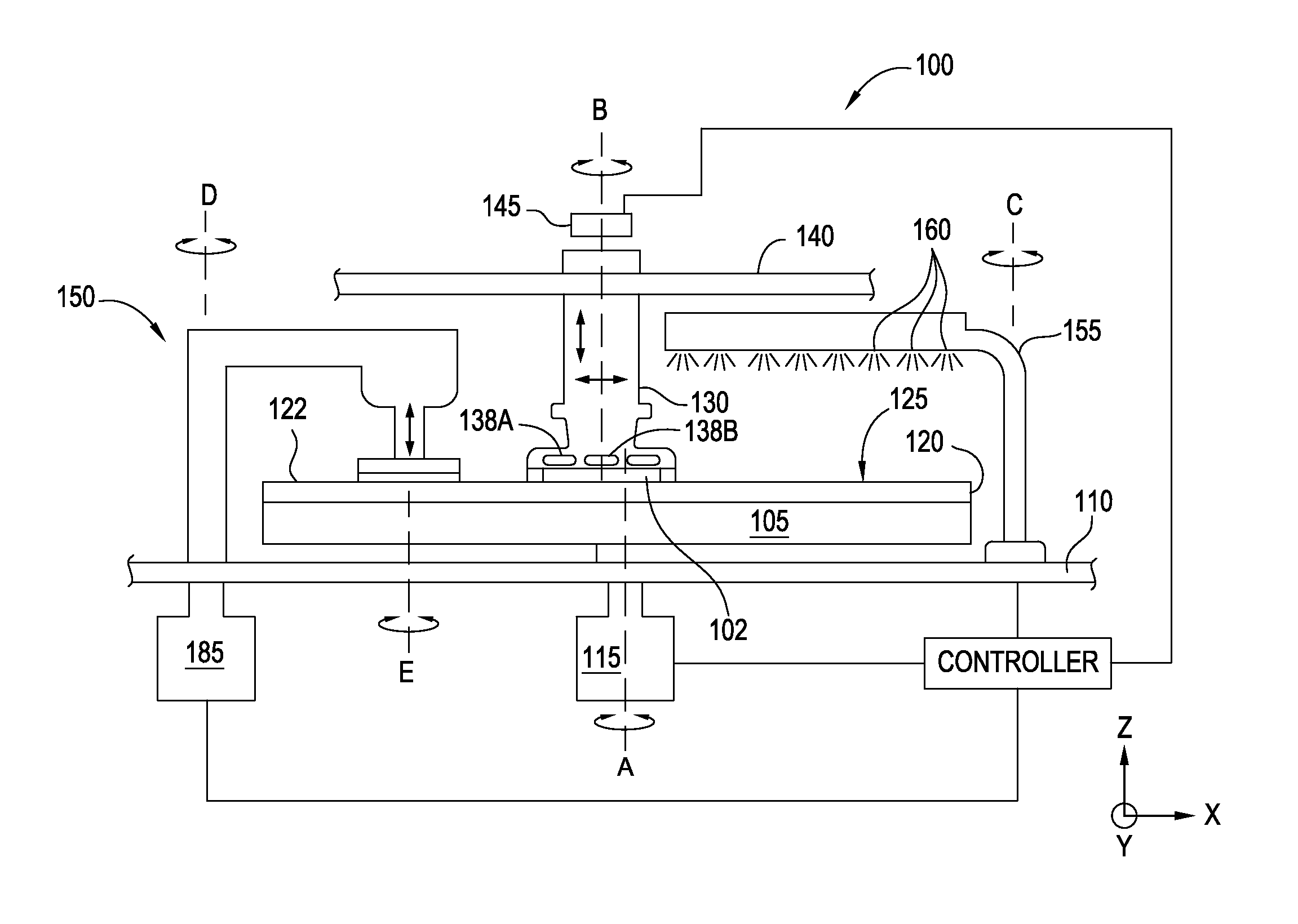
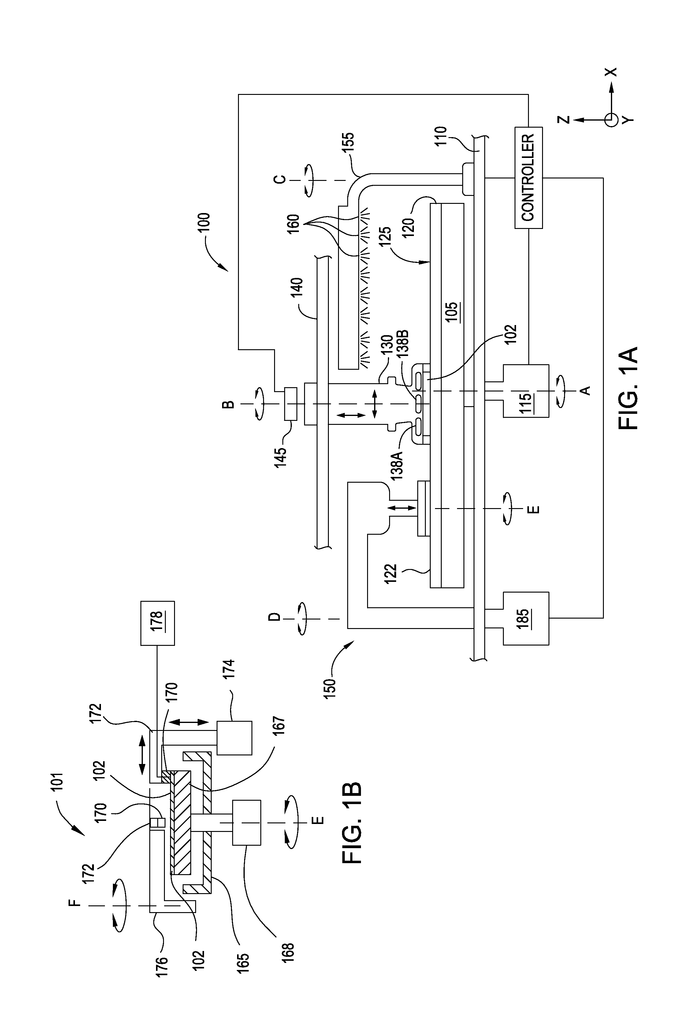
[0029]FIG. 1A is a partial sectional view of one embodiment of a processing station 100 that is configured to perform a polishing process, such as a chemical mechanical polishing (CMP) process ...


PUM


Abstract

A polishing module including a chuck having a substrate receiving surface and a perimeter, and one or more polishing pads positioned about the perimeter of the chuck, wherein each of the one or more polishing pads are movable in a sweep pattern adjacent the substrate receiving surface of the chuck and are limited in radial movement to about less than one-half of the radius of the chuck measured from the perimeter of the chuck.

Description

CROSS-REFERENCE TO RELATED APPLICATIONS[0001]This application claims benefit of U.S. Provisional Patent Application Ser. No. 61 / 894,499 (Atty Docket No. 021009USAL) filed Oct. 23, 2013, which application is hereby incorporated by reference herein.BACKGROUND[0002]1. Field[0003]Embodiments of the present disclosure generally relate to methods and apparatus for polishing a substrate, such as a semiconductor wafer. More particularly, to methods and apparatus for polishing an edge of a substrate in an electronic device fabrication process.[0004]2. Description of the Related Art[0005]Chemical mechanical polishing is one process commonly used in the manufacture of high-density integrated circuits to planarize or polish a layer of material deposited on a substrate by moving a feature side, i.e., a deposit receiving surface, of the substrate in contact with a polishing pad while in the presence of a polishing fluid. In a typical polishing process, the substrate is retained in a carrier head ...

Claims


Application Information

Patent Timeline
IPC IPC(8): B24B37/10B24B7/22H01L21/306B24B53/017
CPCB24B37/10H01L21/30625B24B7/228B24B53/017H01L21/304H01L21/463H01L21/67219
Inventor CHEN, CHIH HUNGBUTTERFIELD, PAUL D.CHANG, SHOU-SUNG
Owner APPLIED MATERIALS INC
Why Eureka
Try Eureka