Vapor deposition device

a vapor deposition device and vapor deposition technology, applied in the field of evaporation apparatus, can solve the problems of warping of the deposition mask, gaps between the substrate, and inability to form a pattern with high placement accuracy, and achieve the effects of reducing stress or warping of the target substrate, improving vapor deposition accuracy, and stably holding the target substra

Inactive Publication Date: 2015-04-30
SHARP KK
View PDF10 Cites 15 Cited by
  • Summary
  • Abstract
  • Description
  • Claims
  • Application Information

AI Technical Summary

Benefits of technology

[0024]As described above, in the evaporation apparatus according to one aspect of the present invention, the substrate holding surface of the substrate holder is curved to match the bend in the target substrate caused by the weight thereof, and thus it is not necessary to hold the target substrate horizontally against the weight thereof. This makes it possible to reduce stress or warping of the target substrate and to stably hold the target substrate, which can lead to an improvement in vapor deposition accuracy. Furthermore, the risk of damage to the target substrate itself is reduced, which allows for an improvement in yield and productivity. The costs of the device can also be reduced.
[0025]The curve of the substrate holder is curved in the direction perpendicular to the scanning direction along the scanning direction, and the substrate holding surface of the substrate holder is uniformly maintained in this curved shape along the scanning direction by scanning along the axis direction of the curve. Therefore, the gap between the target substrate and the deposition mask can be uniformly maintained along the scanning direction during scanning.

Problems solved by technology

This results in warping of the deposition mask due to the weight thereof and stretching, and causes gaps to appear between the substrate on which the film will be deposited and the deposition mask.
As a result, it is not possible to form a pattern with high placement accuracy, which causes deviations in deposition positioning and mixed colors.
This makes achieving a higher resolution difficult.
Furthermore, as substrate sizes become larger, so have the mask frames that hold the deposition mask and the substrate, leading to a substantial increase in weight.
Due to this, not only have the devices for handling these types of deposition masks become much larger, more complicated, and difficult to design, but safety issues in regards to handling these devices occur in the manufacturing process, the process of changing the masks, and the like.

Method used


Image

  • Vapor deposition device
  • Vapor deposition device
  • Vapor deposition device

Examples


embodiment 1

[0038]One embodiment of the present invention will be explained below with reference to FIGS. 1 to 6.

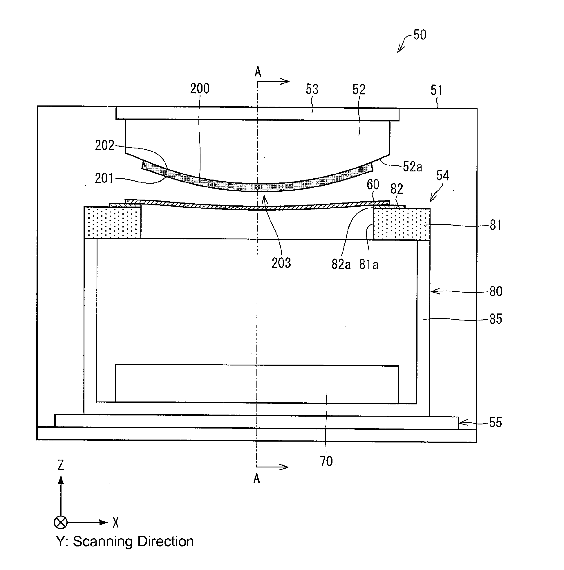
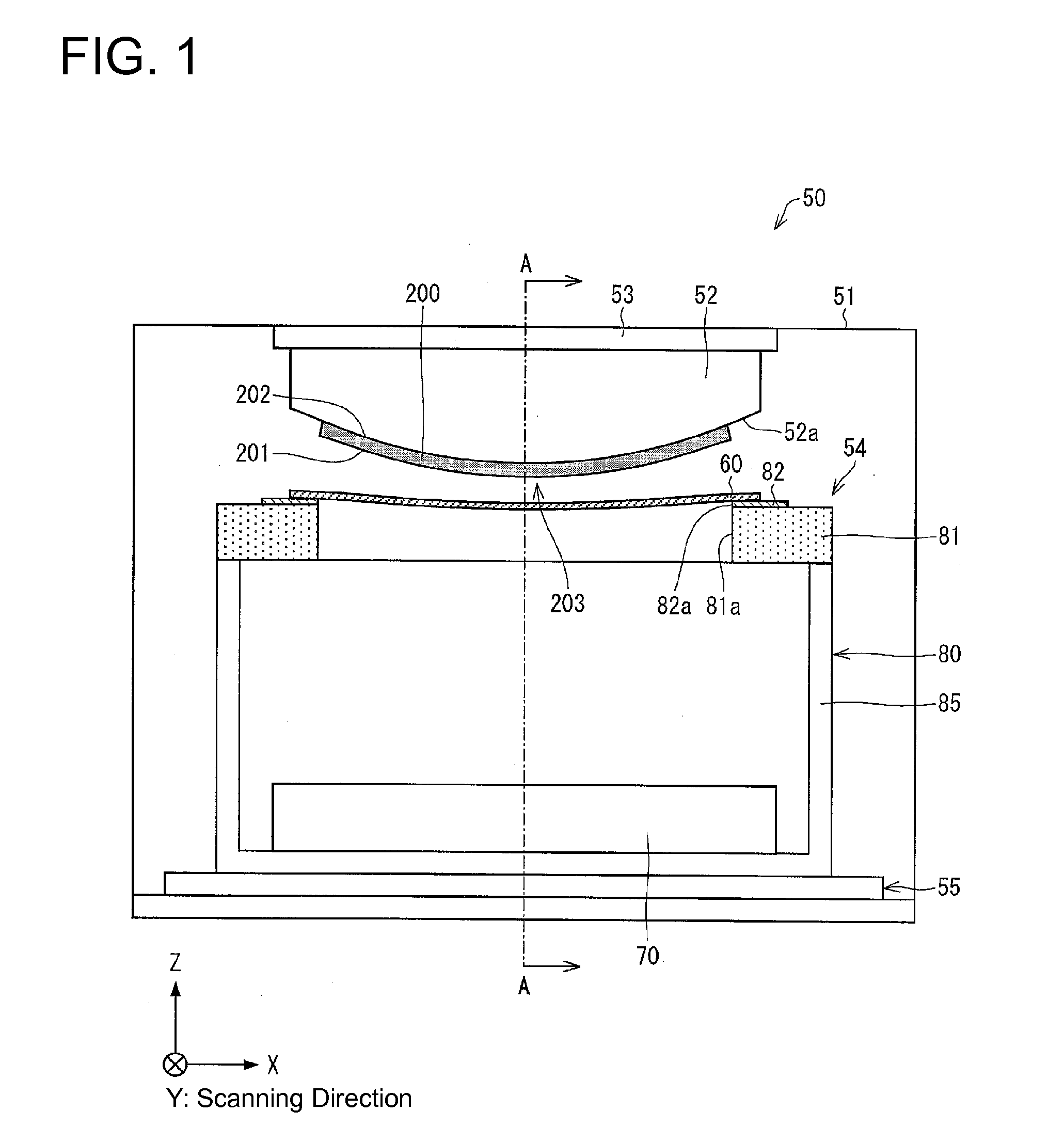
[0039]FIGS. 1 and 2 are both cross-sectional views of a schematic configuration of main parts of an evaporation apparatus according to Embodiment 1.

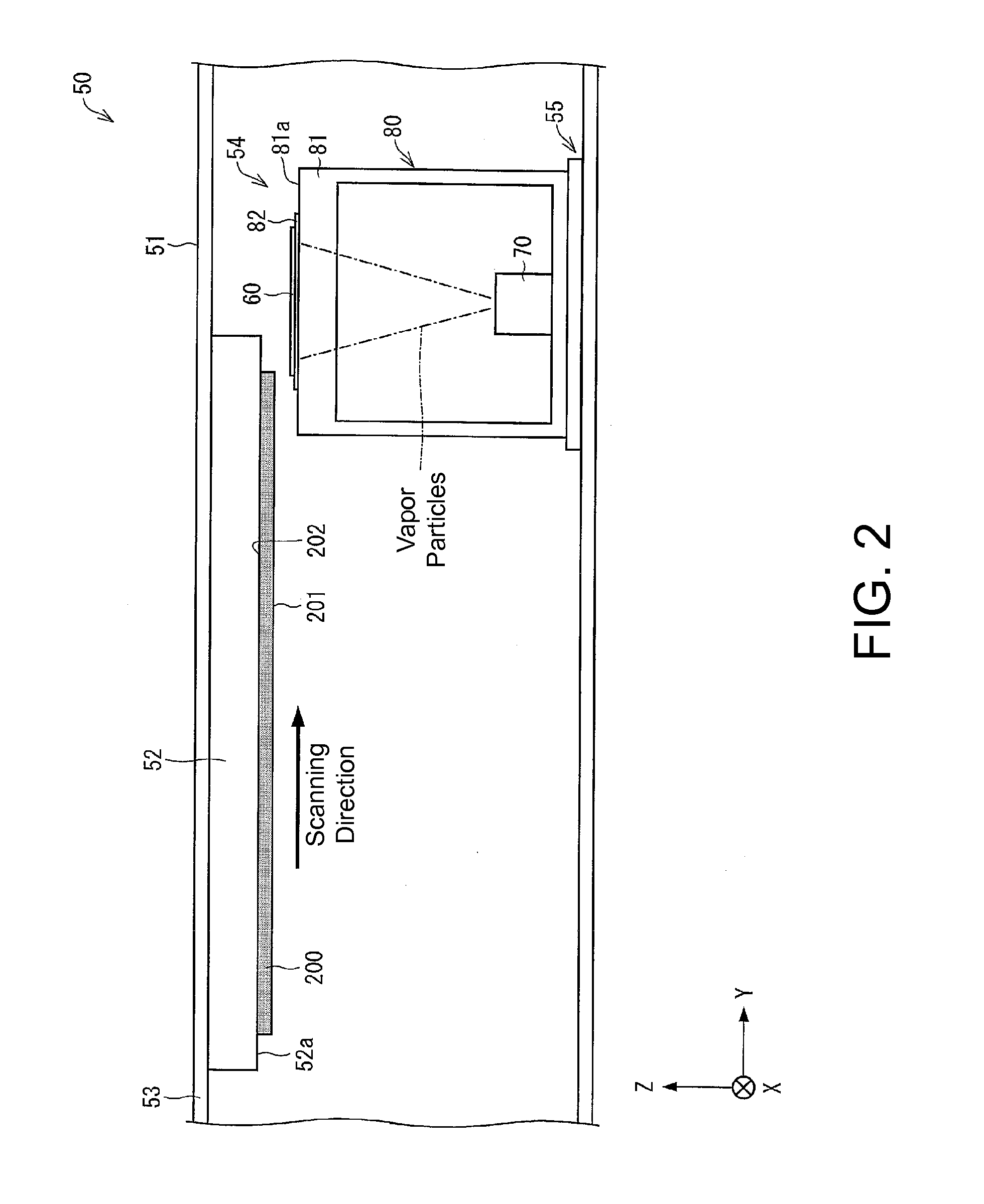
[0040]FIG. 1 shows a cross section of the evaporation apparatus of the present embodiment cut perpendicularly to the scanning direction (substrate scanning direction / first direction), and is equivalent to a cross-sectional view seen from a direction parallel to the scanning direction. Meanwhile, FIG. 2 shows a cross section of the evaporation apparatus of the present embodiment cut parallel to the scanning direction, and is equivalent to a cross-sectional view of the evaporation apparatus in FIG. 1 cut along the line A-A.

[0041]FIG. 3 is an overhead view of the primary constituting elements in a vacuum chamber in the evaporation apparatus according to the present embodiment when see diagonally from above.

[0042]The substrate holder is omitt...

embodiment 2

[0164]The present embodiment will be explained below with reference to FIGS. 7 to 9.

[0165]In the present embodiment, the differences with Embodiment 1 will primarily be explained, and constituting elements and functions that are the same as those used in Embodiment 1 will be given the same reference characters, and a repeat explanation thereof will be omitted.

[0166]FIG. 7 is a schematic cross-sectional view of the arrangement of various deposition elements around a substrate holder 52 in an evaporation apparatus 50 according to the present embodiment. FIG. 7 shows a cross section of the evaporation apparatus 50 according to the present embodiment when cut perpendicularly to the scanning direction. Elements other than the substrate holder 52, target substrate 200, deposition mask 60, mask holder 81, and evaporation source 70 have been omitted.

[0167]In Embodiment 1, an example was described in which the substrate holding surface 52a itself of the substrate holder 52 was curved, or in ...

modification example

[0186]As in Embodiment 1, if the above-mentioned effects can be achieved, there are no particular limitations to the mechanism or shape of the respective parts of the evaporation apparatus 50 and the configurations besides the substrate holder 52, in particular. There are also no particular limitations to the structure of the evaporation source 70, the structure of the entire deposition device 50, and the like, for example. It is possible for modifications similar to Embodiment 1 to be performed.

[0187]Accordingly, the order of the substrate delivery process can be changed to be similar to Embodiment 1. Furthermore, support members other than the pins 101 may be used as the support members, in a manner similar to Embodiment 1.

[0188]In the present embodiment, an example was described in which the substrate holding surface 52a of the substrate 52 has two curves 52A in the direction perpendicular to the scanning direction, but the substrate holding surface 52a of the substrate holder 52...


PUM

PropertyMeasurementUnit
heightaaaaaaaaaa
heightaaaaaaaaaa
thicknessaaaaaaaaaa

Abstract

In a deposition device, a deposition mask of a mask unit (54) has a width in the scanning (movement) direction thereof that is less than a width of a target substrate (on which film will be deposited) in the same scanning direction. A substrate holder includes a substrate holding surface that has at least one curve along the scanning direction matching a bend in the target substrate caused by the weight thereof, and this curve occurs in the direction perpendicular to the scanning direction.

Description

TECHNICAL FIELD[0001]The present invention relates to an evaporation apparatus that performs deposition using a deposition mask of which at least one side thereof is smaller than the substrate on which the film is formed (i.e., the target substrate).BACKGROUND ART[0002]In recent years, flat-panel displays have been used in various products and fields, and there is demand for the flat-panel displays to be larger, to have higher resolution, and to consume less power.[0003]Organic EL display devices having organic EL elements that use electroluminescence (hereinafter, “EL”) from organic materials have attracted heightened attention in this regard, due to being completely solid-state, having excellent low-voltage driving, fast response speed, emitting light on its own, and other advantages.[0004]An organic EL display device has organic elements that are connected to TFTs (thin film transistors) and arranged on a substrate that is constituted of a glass substrate or the like, for example...

Claims


Application Information

Patent Timeline
Patent Type & Authority Applications(United States)
IPC IPC(8): C23C14/24C23C14/50C23C14/04
CPCC23C14/243C23C14/50C23C14/042C23C14/24C23C14/12C23C14/562H10K71/164H10K71/166H10K71/00
Inventor KAWATO, SHINICHIKIKUCHI, KATSUHIRONIBOSHI, MANABUOCHI, TAKASHITSUKAMOTO, YUTOKOSAKA, TOMOHIROOSAKI, TOMOFUMI
Owner SHARP KK
Why Eureka
Try Eureka