Laser scanning microscope apparatus and laser scanning method

a laser scanning and microscope technology, applied in the field of laser scanning microscope equipment and laser scanning method, can solve the problems of difficult to observe specimens in detail at the desired light intensity, and the fine adjustment of laser light intensity

Active Publication Date: 2015-04-30
EVIDENT CORP
View PDF5 Cites 2 Cited by
  • Summary
  • Abstract
  • Description
  • Claims
  • Application Information

AI Technical Summary

Benefits of technology

[0031]The present invention affords an advantage in that it is possible to realize both light stimulation of a specimen at a high intensity and detailed fluorescence observation thereof at a low intensity by using a single laser light source.

Problems solved by technology

Because of this, the laser-light intensity cannot be finely adjusted when attempting to perform fluorescence observation at a low intensity, which makes it difficult to observe a specimen in detail at a desired light intensity.

Method used


Image

  • Laser scanning microscope apparatus and laser scanning method
  • Laser scanning microscope apparatus and laser scanning method
  • Laser scanning microscope apparatus and laser scanning method

Examples


Embodiment Construction

[0039]A laser scanning microscope apparatus and a laser scanning method according to an embodiment of the present invention will be described below with reference to the drawings.

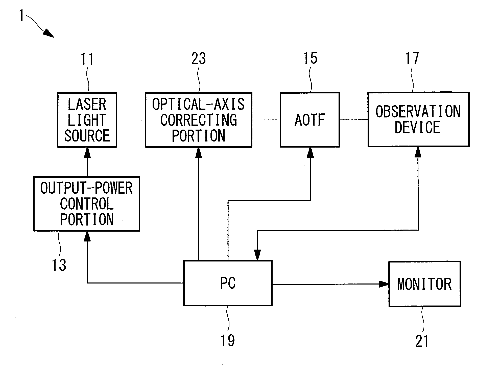
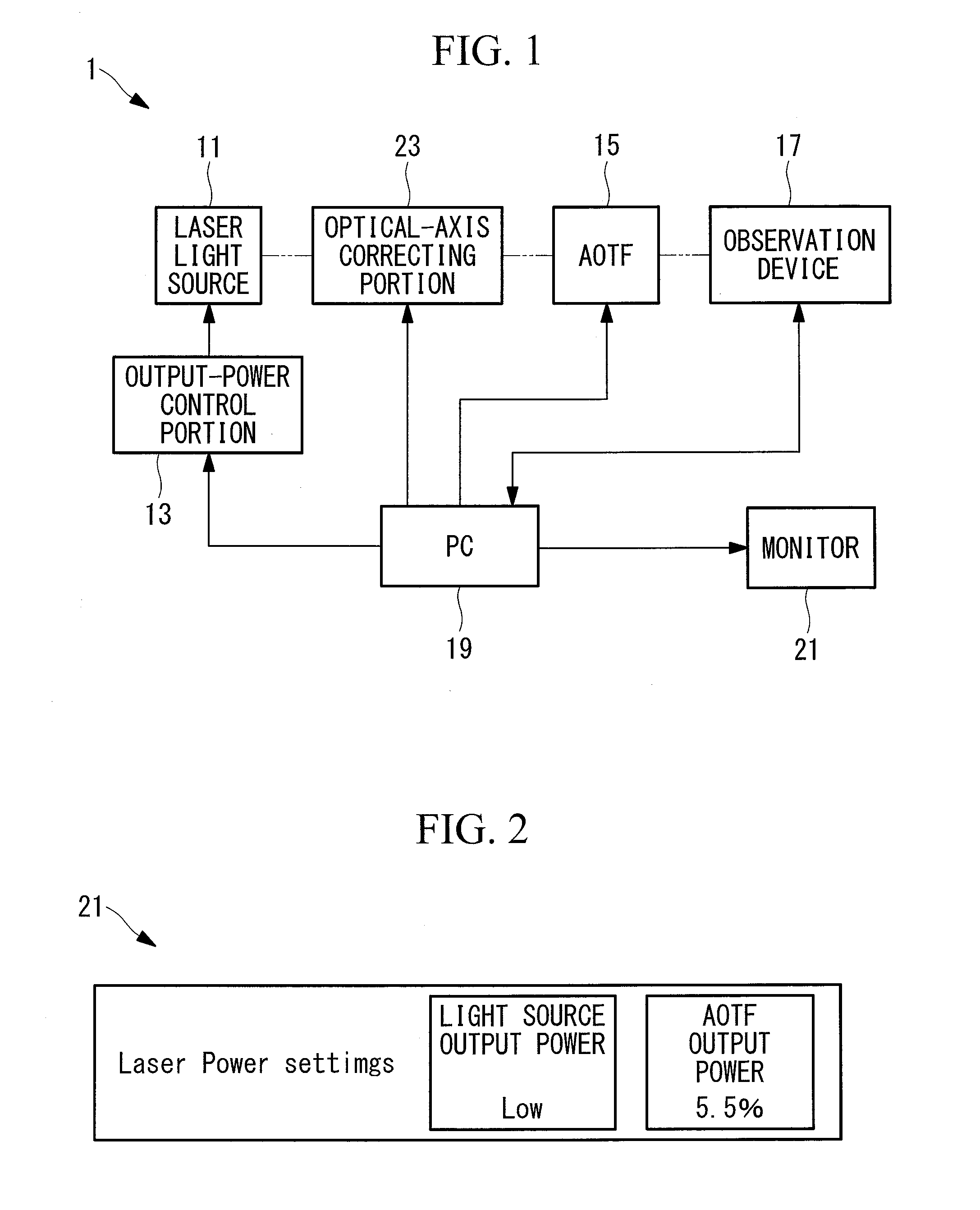
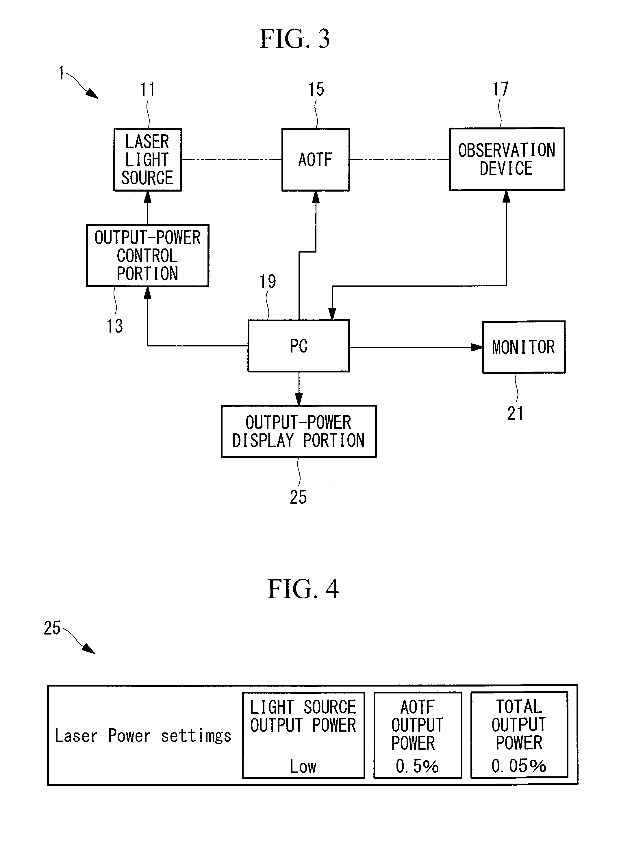
[0040]As shown in FIG. 1, a laser scanning microscope apparatus 1 according to this embodiment is provided with a laser light source (light source) 11 that generates laser light; an output-power control portion 13 that sets the output power of the laser light source 11 by changing it in a step-wise manner; an AOTF (Acoust-Optic Tunable Filter, light-level control portion, acoust-optic device) 15 that adjusts the light level of the laser light emitted from the laser light source 11 in a step-wise manner; an observation device (observation portion) 17 that acquires image information of a specimen by irradiating a specimen (not shown) with the laser light whose light level has been adjusted by the AOTF 15; a PC (Personal Computer) 19 having control software for controlling the output-power control portion 13, ...


PUM

PropertyMeasurementUnit
laser scanning microscopeaaaaaaaaaa
output poweraaaaaaaaaa
fluorescenceaaaaaaaaaa

Abstract

Both light stimulation of a specimen at a high intensity and detailed fluorescence observation at a low intensity are realized by using a single laser light source. Provided is a laser scanning microscope apparatus (1) including a laser light source (11) that generates laser light; output-power control portion (13) that can set an output power of the laser light source (11) by changing the output power in a step-wise manner; an AOTF (15) that can adjust a light level of the laser light emitted from the laser light source (11) in a step-wise manner at a resolution that is finer than a resolution at which the output-power control portion (13) changes the output power of the laser light source (11); and an observation device (17) that scans the laser light whose light level has been adjusted by the AOTF (15) on a specimen and that detects fluorescence generated at the specimen.

Description

CROSS-REFERENCE TO RELATED APPLICATIONS[0001]This application is based on Japanese Patent Application No. 2013-225636, the contents of which are incorporated herein by reference.TECHNICAL FIELD[0002]The present invention relates to a laser scanning microscope apparatus and a laser scanning method.BACKGROUND ART[0003]In the related art, there is a known laser microscope with which light stimulation and fluorescence observation a specimen are performed (for example, see Patent Literature 1). A relatively high light intensity is required in order to obtain a response when performing light stimulation of a specimen, whereas a relatively low light intensity is often demanded for fluorescence observation in order to avoid color fading.[0004]A laser microscope disclosed in Patent Literature 1 is provided with an acousto-optic device like an AOTF (Acoust-Optic Tunable Filter), and the intensity of laser light is modulated by using the acousto-optic device when performing light stimulation a...

Claims


Application Information

Patent Timeline
Patent Type & Authority Applications(United States)
IPC IPC(8): G02B21/00G02B21/16G02F1/11G02B21/06
CPCG02B21/002G02B21/16G02B21/06G02B21/0032G02F1/116
Inventor MORI, KEIGO
Owner EVIDENT CORP
Why Eureka
Try Eureka