
Radiosonde power source device and radiosonde

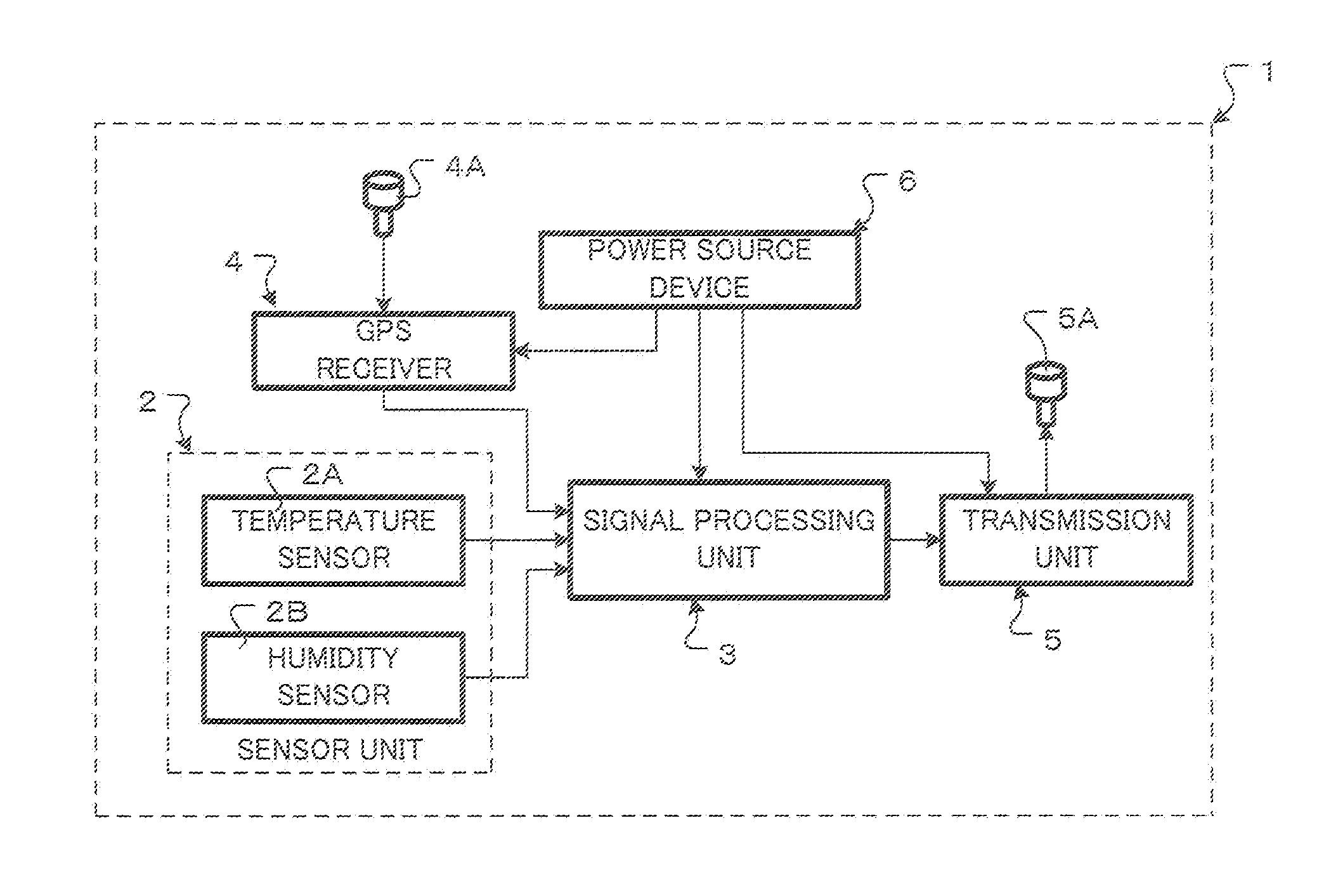
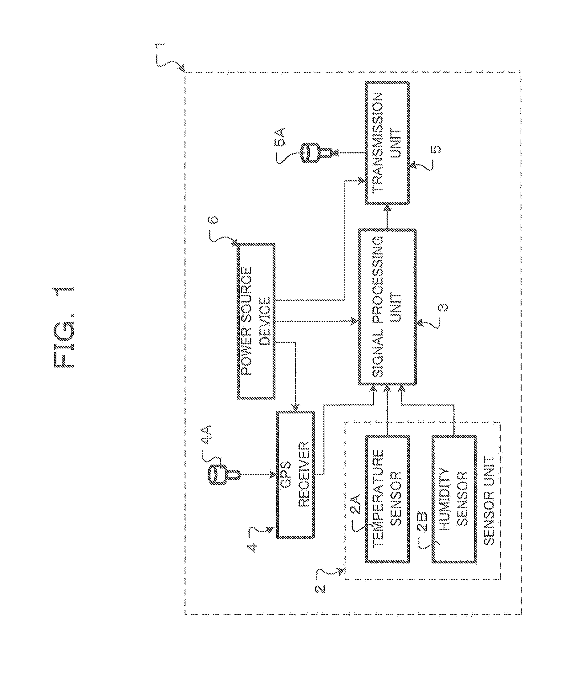
a power source device and radiosonde technology, applied in secondary cell servicing/maintenance, instruments, transportation and packaging, etc., can solve the problems of increasing the weight of the power source device, increasing the volume of balloons, and inconvenience in operation, so as to reduce the number of dry cells, reduce the weight of the radiosonde, and reduce the size

Inactive Publication Date: 2015-05-07
MEISEI ELECTRIC
View PDF6 Cites 4 Cited by
  • Summary
  • Abstract
  • Description
  • Claims
  • Application Information

AI Technical Summary

Benefits of technology

The radiosonde power source apparatus described in this patent can increase the voltage of a dry cell using a step-up power source circuit, allowing the radiosonde to perform observations with the electric capacity of one cell. This design reduces the number of dry cells needed, making the radiosonde lighter and easier to release. Additionally, the design prevents self-heating, which can cause voltage drops in the dry cell, by allowing the ambient temperature to decrease as the altitude increases. This results in a stable voltage supply.

Problems solved by technology

However, the water-activated battery has sometimes caused operational inconvenience because its operation cannot be stopped once water is injected.
However, if a plurality of dry cells are used in the power source unit of the radiosonde, the power source device increases in weight.
The balloon also becomes larger in volume, and the gas volume of hydrogen gas or the like filled into the balloon increases to increase the cost needed for a release.
If manganese or alkali dry cells are used, the aqueous electrolyte solution inside can freeze and cause a voltage drop in low temperature environments.
The use of a plurality of lithium batteries connected in series translates into mounting an electric capacity more than necessary, resulting in wasted cost.

Method used


Image

  • Radiosonde power source device and radiosonde
  • Radiosonde power source device and radiosonde
  • Radiosonde power source device and radiosonde

Examples


second embodiment

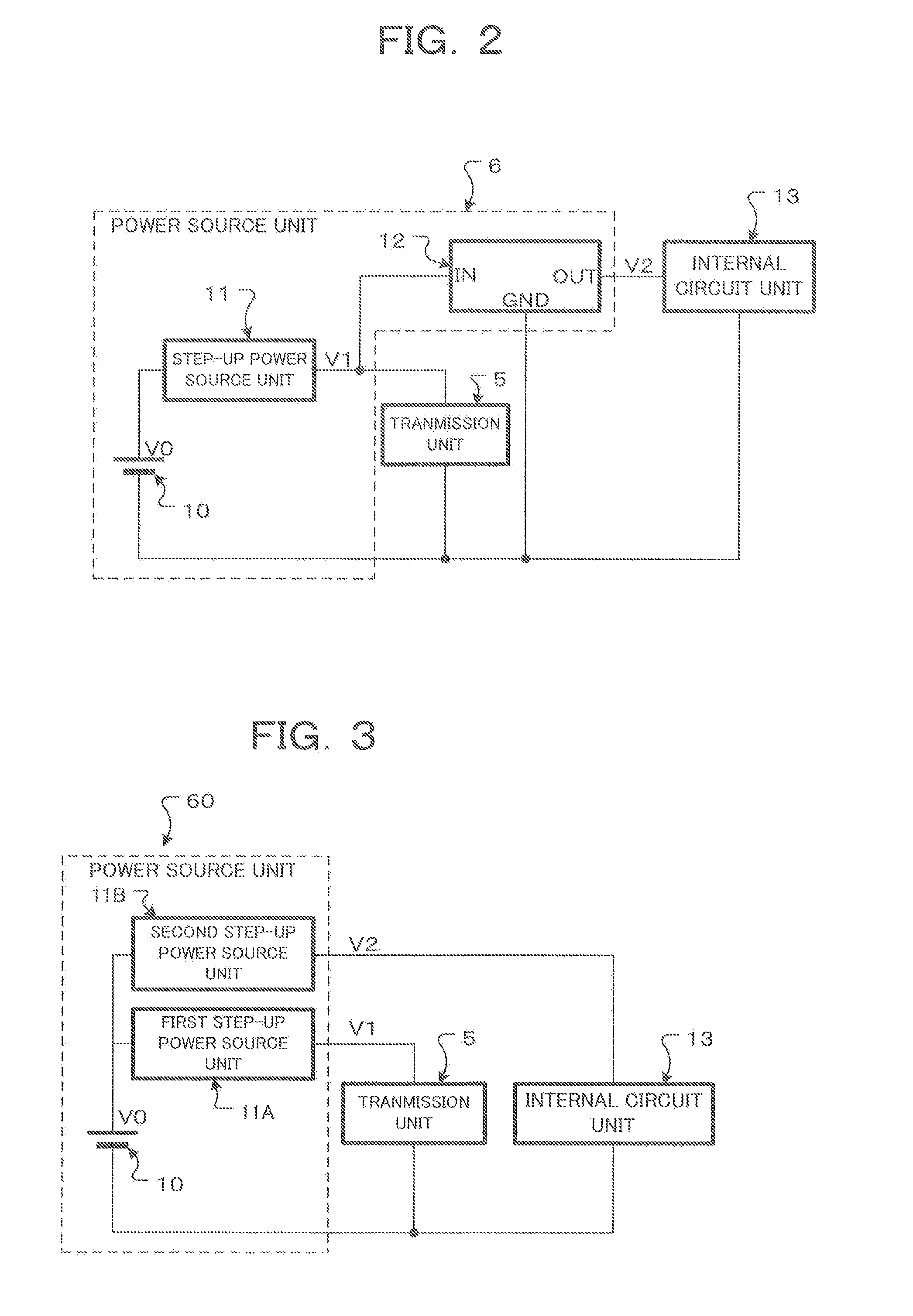
[0046]FIG. 3 is a block diagram showing a second embodiment of the power source device of the radiosonde shown in FIG. 1.

[0047]In the first embodiment shown in FIG. 2, the regulator 12 is used to drive the internal circuit unit 13. In the present embodiment, a voltage V2 stepped up by a second step-up power source circuit 11B having the same configuration as that of the step-up power source circuit 11 is supplied to the internal circuit 13. A voltage V1 stepped up by a first step-up power source circuit 11A having the same configuration as that of the step-up power source circuit 11 is supplied to the transmission unit 5

[0048]In the present embodiment, the voltage V0 of one dry cell 10 is stepped up to the voltages V1 and V2 (V211A and the second step-up power source circuit 11B, respectively. If there is provided a circuit unit to be driven by a voltage different from the voltages V1 and V2, a new step-up power source circuit may be added to supply a voltage V3. The number of step-...


PUM


Abstract

The present invention can be made more lightweight even if a dry cell is used as a power source battery, can supply a necessary voltage at a battery capacity corresponding to an observation time, and can generate a predetermined electromotive force even in extremely low-temperature environments, This radiosonde power source device supplies driving electrical power to an apparatus tor processing and transmitting observation information resulting from, observing meteorological phenomena of the upper atmosphere, and has; a dry cell such as a lithium battery having a rated voltage lower than the driving voltage of the apparatus; and one or more step-up power source circuits that step-up the voltage of the dry cell to a predetermined voltage.

Description

TECHNICAL FIELD[0001]The present invention relates to a power source device mounted on a radiosonde which is flown on a balloon to make meteorological observations in the upper air.BACKGROUND ART[0002]A radiosonde for observing the upper atmosphere measures a wind direction, wind speed, atmospheric pressure, temperature, and humidity in the upper atmosphere, and transmits measurement information to the ground by using a transmitter. A water-activated battery has conventionally been used as a main power source of a power source device for driving the equipment of the radiosonde. The reason is that the water-activated battery suitably satisfies requirements such as having a sufficient voltage (approximately 5 V to 1.2 V) to operate the transmitter of the radiosonde, being operable at surface temperatures and in extremely low temperature environments of near −90° C. up in the air, and having a weight light enough to be flown on a rubber balloon.[0003]By the way, the water-activated bat...

Claims


Application Information

Patent Timeline
IPC IPC(8): H02J7/00G01W1/08
CPCG01W1/08H02J7/007H01M10/44H02J2207/20Y02E60/10
Inventor SHIMIZU, KENSAKU
Owner MEISEI ELECTRIC
Learn More