Method for diagnosing faults in slurry pump impellers

a technology of slurry pump and impeller, which is applied in the direction of testing/monitoring control system, instruments, testing/dynamic balance measurement, etc., can solve the problems of restricting reducing costs, so as to reduce costs, restrict the ability to plan maintenance, and increase the lifespan of the impeller

Inactive Publication Date: 2015-05-07
SYNCRUDE CANADA LTD +1
View PDF16 Cites 24 Cited by
  • Summary
  • Abstract
  • Description
  • Claims
  • Application Information

AI Technical Summary

Benefits of technology

[0009]It was initially believed that the remaining life of impellers may be determined by head ratio which predicts pump failure but provides only limited warning, thus restricting the ability to plan maintenance and reduce costs.
[0010]However, it was discovered that vibration data collected from pumps during operation can be used to calculate specific indicators which demonstrate consistent polynomial or linear fault trends that reflect the conditions of impellers. In particular, the indicators may include energy level, crest factor, square root amplitude value, and fault growth parameter. Further, the high frequency component in frequency spectra may also be used to reflect the conditions of impellers. It was also discovered that applying specific prediction methods to the collected vibration data may predict the remaining useful life of the impeller. Accordingly, detecting the wear and increasing the lifespan of the impeller can be greatly beneficial in maintaining pump performance and meeting production targets.

Problems solved by technology

It was initially believed that the remaining life of impellers may be determined by head ratio which predicts pump failure but provides only limited warning, thus restricting the ability to plan maintenance and reduce costs.

Method used


Image

  • Method for diagnosing faults in slurry pump impellers
  • Method for diagnosing faults in slurry pump impellers
  • Method for diagnosing faults in slurry pump impellers

Examples


example 1

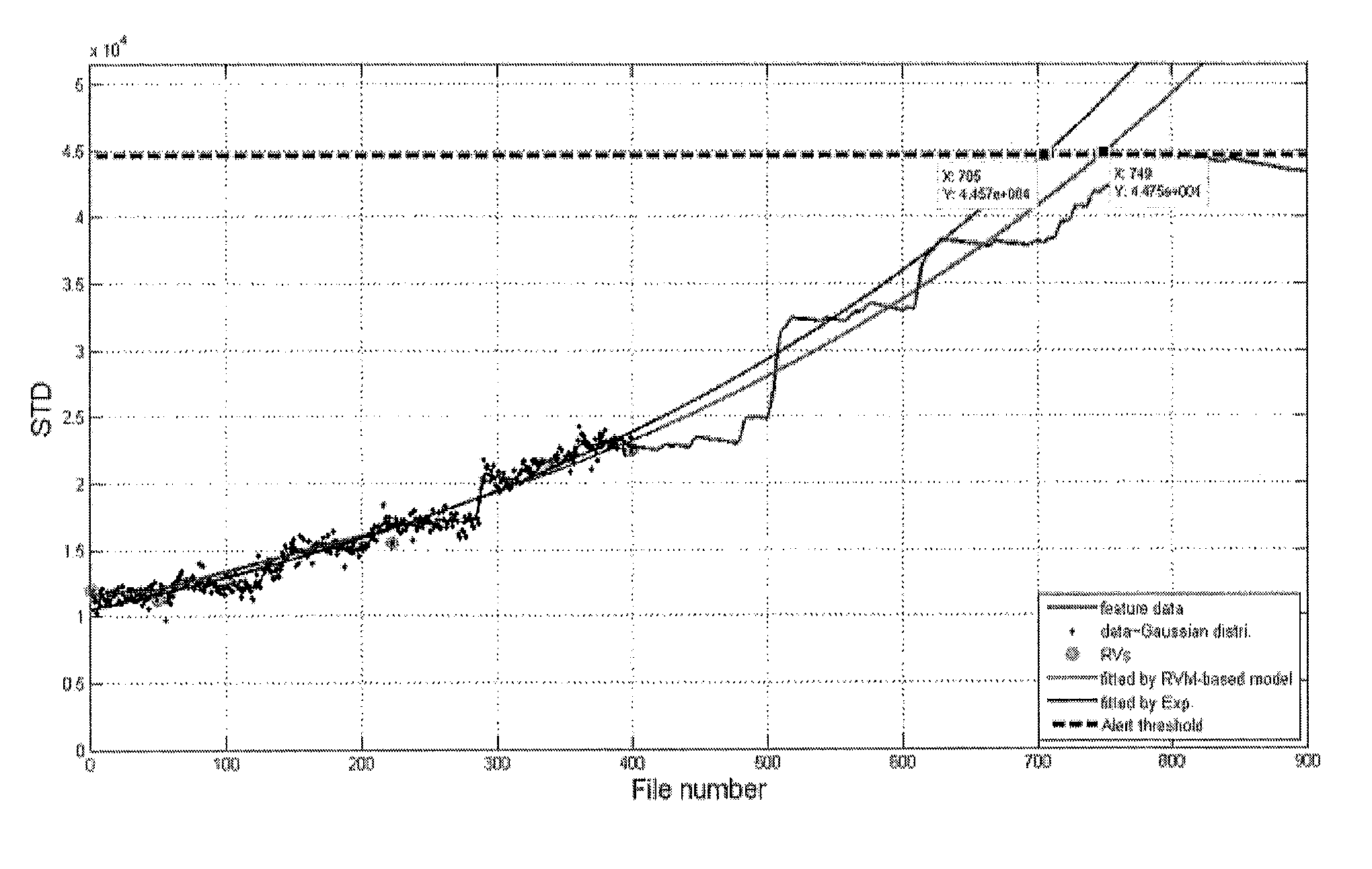
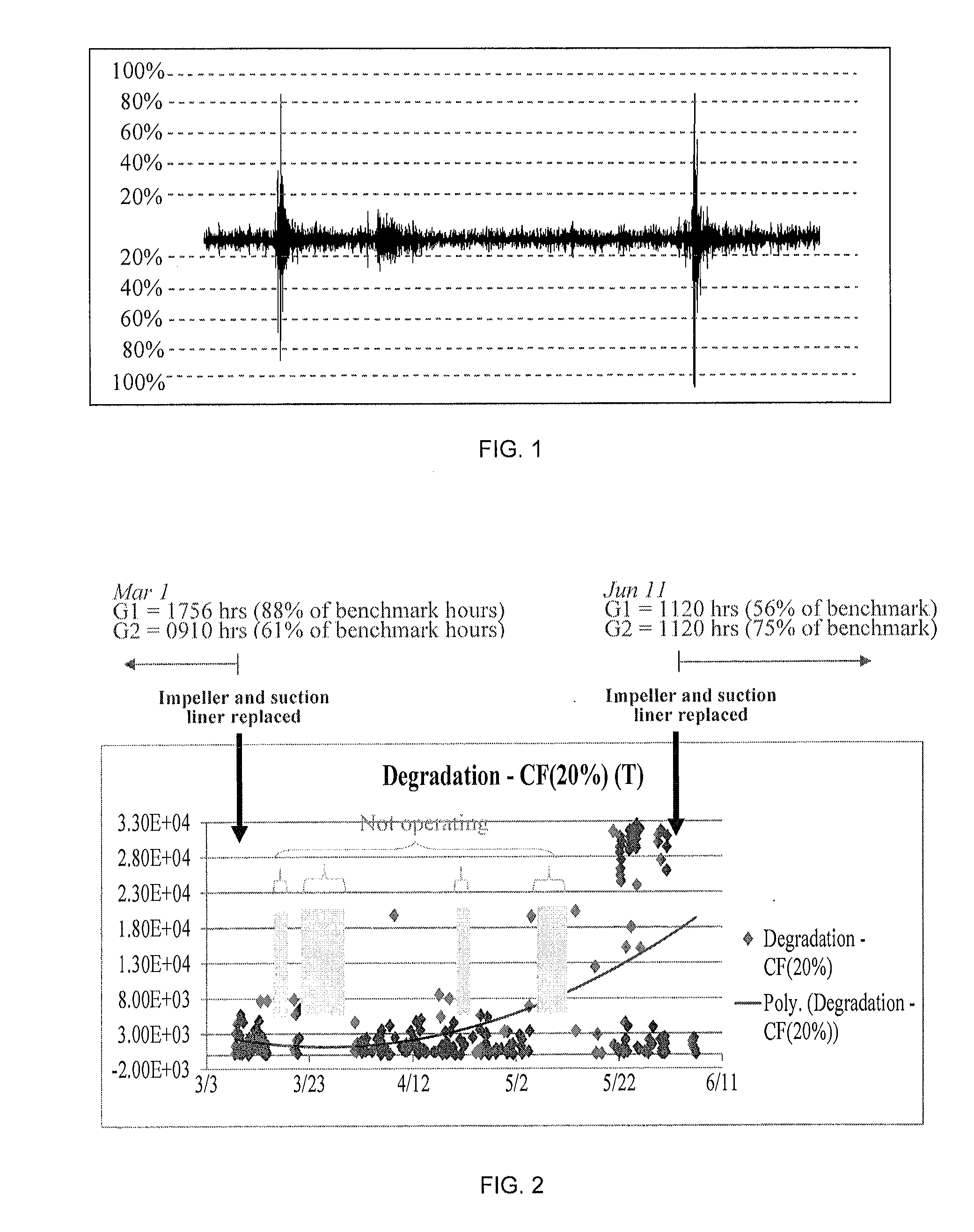
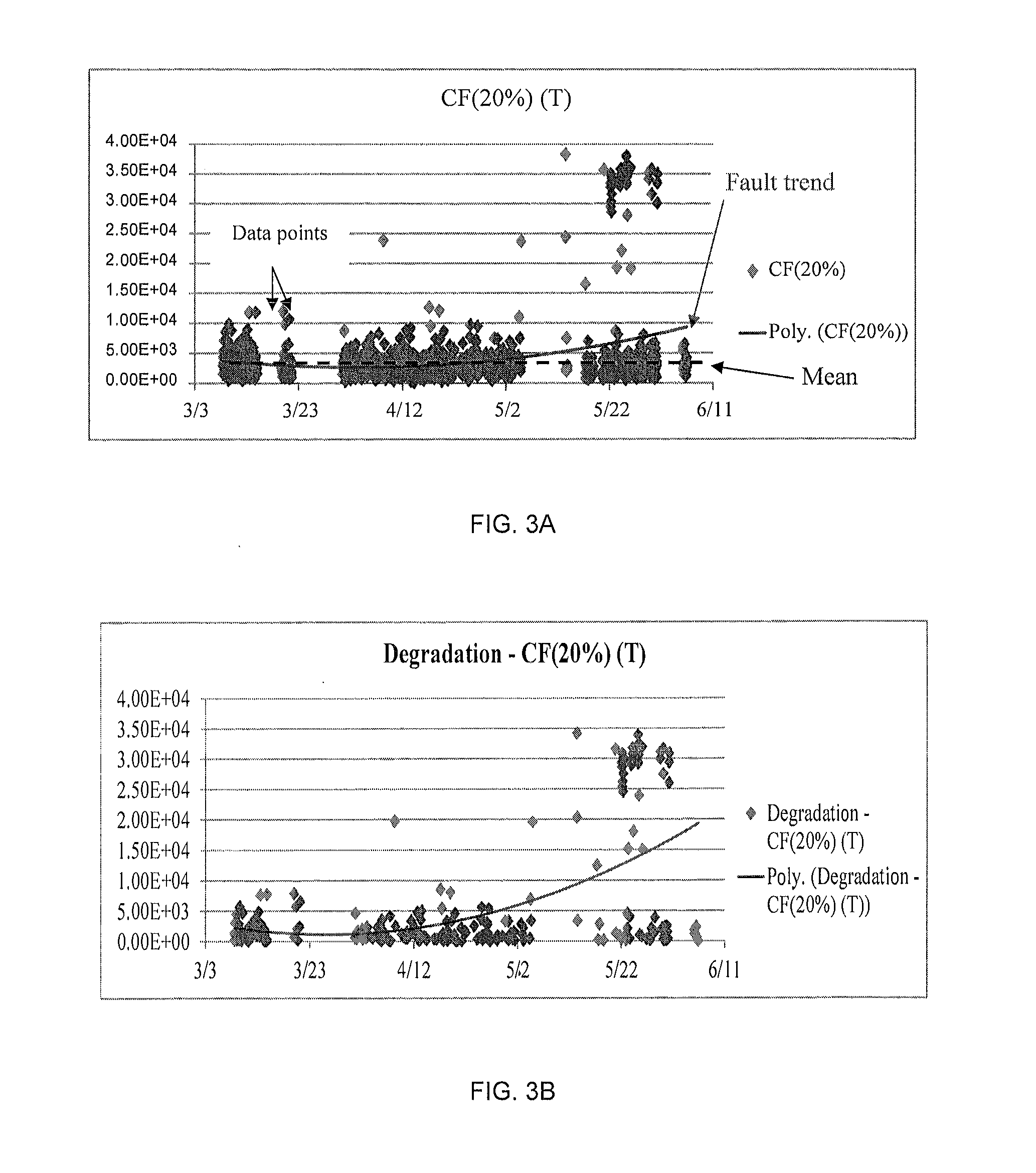
[0076]Field vibration data were used to diagnose the conditions of slurry pumps. The data were collected from thirty-two accelerometers capable of detecting vibrations having frequencies between 5 Hz to 60 kHz (PCB Piezotronics; part #352A60), and installed on the casings of eight slurry pumps (designated as Train 2(237-2G): G1, G2, G4 and G5; and Train 3(237-3G): G1, G2, G4, and G21). Each pump was instrumented with four accelerometers connected to stand-alone data loggers, of which six were deployed in the field at the different pump houses. Logging sessions were scheduled once per hour (later at every 30 minutes) to log signals for 1 second at 50 kHz sampling frequency. Later, sampling frequency was increased to 60 kHz to use the full frequency range of the accelerometers.

[0077]Vibration data files were recorded in time domain waveform onto the hard drives of the data loggers. The data files were then retrieved from the data loggers for post-processing and evaluation of indicator...


PUM


Abstract

A method of diagnosing the condition of a slurry pump impeller is provided, comprising collecting vibration data from at least one accelerometer mounted to or proximate the pump over a specific time period; calculating indicators from the collected vibration data, the indicators comprising energy level, crest factor, square root amplitude value, and fault growth parameter; and plotting the calculated indicators against time to generate a fault trend indicative of health or deterioration of the impeller. The method further involves predicting the remaining useful life of the impeller using vibration data-driven prognostics.

Description

FIELD OF THE INVENTION[0001]The present invention relates generally to a method of diagnosing the condition of an impeller of a slurry pump, and predicting the remaining useful life of the impeller.BACKGROUND OF THE INVENTION[0002]A conventional centrifugal slurry pump generally includes an impeller having multiple vanes and which is mounted for rotation within a volute casing. The slurry pump imparts energy to the slurry through the centrifugal force produced by rotation of the impeller. The slurry enters into the impeller through an intake conduit positioned in line with the rotating axis and is accelerated by the impeller, flowing radially outward into the volute casing and subsequently exiting through a discharge conduit. A suction sideliner is positioned a predetermined short distance away from the impeller suction side, the distance being so small as to substantially preclude slurry flow between the impeller and the suction sideliner.[0003]Slurries are two-phase mixtures of so...

Claims


Application Information

Patent Timeline
Patent Type & Authority Applications(United States)
IPC IPC(8): F04D27/00G01H1/00F04D7/04
CPCF04D27/001G01H1/003F04D7/04F04D15/0088G05B23/0283
Inventor OBAIA, KHALEDWOLFE, DANLANGE, STEFFENTSE, PETER W.LEUNG, JACKO T.
Owner SYNCRUDE CANADA LTD
Why Eureka
Try Eureka