Chute system with adjustable angle of inclination

a chute system and inclination angle technology, applied in the direction of conveyors, adaptive control, instruments, etc., can solve the problems of not being able to receive one or more additional objects, affecting the sorting system, and affecting the sorting effect, so as to increase the vertical level, and reduce the inclination angle

Inactive Publication Date: 2015-05-07
CRISPLANT
View PDF14 Cites 11 Cited by
  • Summary
  • Abstract
  • Description
  • Claims
  • Application Information

AI Technical Summary

Benefits of technology

[0011]Such chute system is advantageous, since it is possible to handle sticky objects on a simple gravity chute which can have a rather low angle of inclination, e.g. 10-15° or even lower, during normal operation. When a sticky object, e.g. a piece of poly wrapped luggage, stops on the chute section, the displacement means can increase the vertical level of the inlet so as to increase the angle of inclination of the chute section to a point where the gravity causes the sticky objects to start moving. If an object moves too fast on a chute section, the angle of inclination can be lo

Problems solved by technology

However, it is a problem with such chute systems that objects, e.g. pieces of luggage, can have significantly different surface properties.
In that a chute is a destination from which objects moved by the sorter is to be discharged into at a discharge position, an object stopped unintentionally in the chute, or an object not moving with a certain range of speed in the chute, e.g. moving too slow in the chute, may, e.g., cause unwanted recirculations in the sorting system.
This is due to the chute then no lo

Method used


Image

  • Chute system with adjustable angle of inclination
  • Chute system with adjustable angle of inclination
  • Chute system with adjustable angle of inclination

Examples


Embodiment Construction

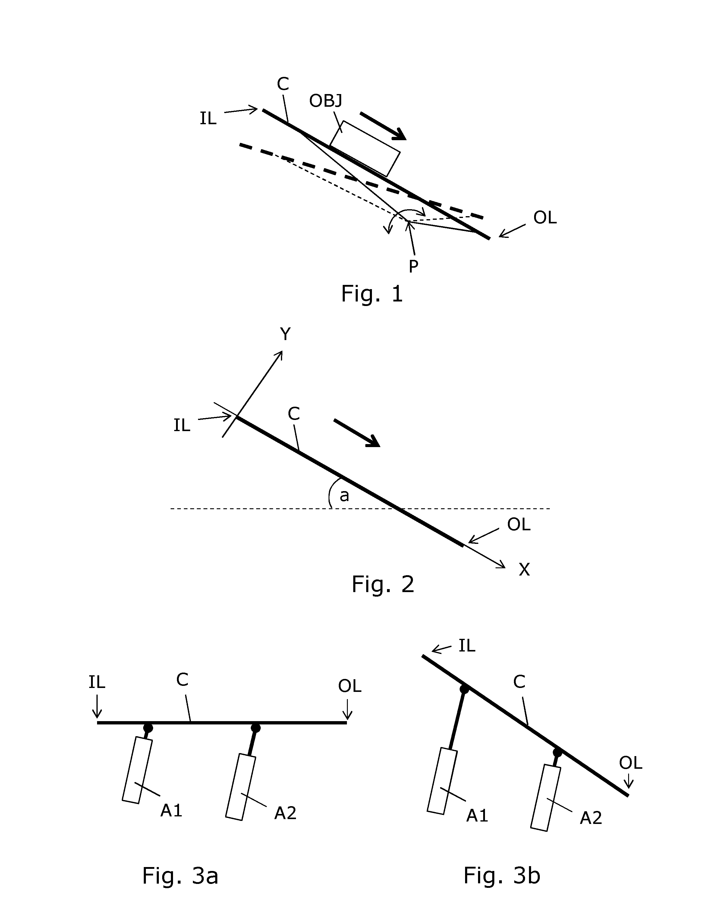
[0054]FIG. 1 illustrates a side view sketch of a chute section embodiment in the form of a simple gravity chute with a planar chute surface C on which an object OBJ can slide from an inlet IL to an outlet OL in the direction indicated by the arrow. The chute surface C is connected to a structure which is hinged so as to allow pivoting around a pivot point P downstream of the inlet IL, thereby adjusting or changing the angle of inclination of the chute surface C. The dashed lines indicates the chute structure displaced by pivoting around the pivot point P into a position with a smaller angle of inclination. This is one way of providing a displacement of the inlet IL of the chute with respect to its vertical level. It is seen that the inlet IL of the solid version of the chute is at a higher vertical level than the inlet of the dotted version of the chute.

[0055]Displacement means (not shown) preferably comprising an actuator, is used to displace the chute structure between one angle o...


PUM


Abstract

The invention provides a chute system (C1,C2,C3) for a sorting system arranged for transporting objects, e.g. for use for discharging luggage from a conveyor system. The chute system has one or more chute sections with an inlet (IL) in one end and an outlet (OL) in the opposite end. Displacement means, e.g. a pneumatic actuator, is arranged to adjust an angle of inclination of the one or more chute sections (C1,C2,C3) by displacing the chute section (C1,C2,C3) in a motion comprising pivoting around a pivot point positioned downstream of the inlet (IL). E.G. the pivot point can be positioned at the outlet, e.g. by means of a hinge. The adjustment of the angle of inclination may be controlled by a processor in response to various position and/or speed sensors and/or information about incoming objects from a vision based system or from the associated sorting system, e.g. identification of poly wrapped objects. The angle of inclination can be increased in case an object stops on the chute section, or the angle of inclination can be decreased in case an object moves too fast, even if a simple gravity chute is used. A cascade of two or more chute sections (C1,C2,C3) with adjustable angles of inclination can be used to control batches of objects and to control back pressure of objects on the chute.

Description

FIELD OF THE INVENTION[0001]The invention relates to the field of handling and sorting of objects or materials, such as luggage or parcels or the like. In particular, the invention provides a chute system with an adjustable angle of inclination for use in a sorting system.BACKGROUND OF THE INVENTION[0002]Chutes are used in sorting systems typically for discharging objects from a conveyor system. For example, chutes are used in luggage sorting and transporting systems in an airport, however chutes are also used for objects larger than luggage or for objects smaller than luggage. Often, a chute system is implemented using simple plates or passive rollers or the like, set up with an angle of inclination so as to allow objects to slide thereon by means of gravity. However, it is a problem with such chute systems that objects, e.g. pieces of luggage, can have significantly different surface properties. Some objects have a surface with a high stick and slip effect, e.g. poly wrapped items...

Claims


Application Information

Patent Timeline
IPC IPC(8): B65G11/12B65G11/20B07C5/36B65G11/08B65G47/28B65G11/02
CPCB65G11/123B65G47/28B65G11/203B07C5/36B65G11/081B65G11/023B65G47/26G05B13/021
Inventor LYKKEGAARD, UFFEPEDERSEN, FINN LYNG
Owner CRISPLANT
Why Eureka
Try Eureka