Laser enclosure

Active Publication Date: 2015-05-07
LINCOLN GLOBAL INC
View PDF10 Cites 9 Cited by
  • Summary
  • Abstract
  • Description
  • Claims
  • Application Information

AI Technical Summary

Problems solved by technology

However, in light of the fact that the laser is positioned in close proximity to the welding gun, the lens o

Method used


Image

  • Laser enclosure
  • Laser enclosure
  • Laser enclosure

Examples


Embodiment Construction

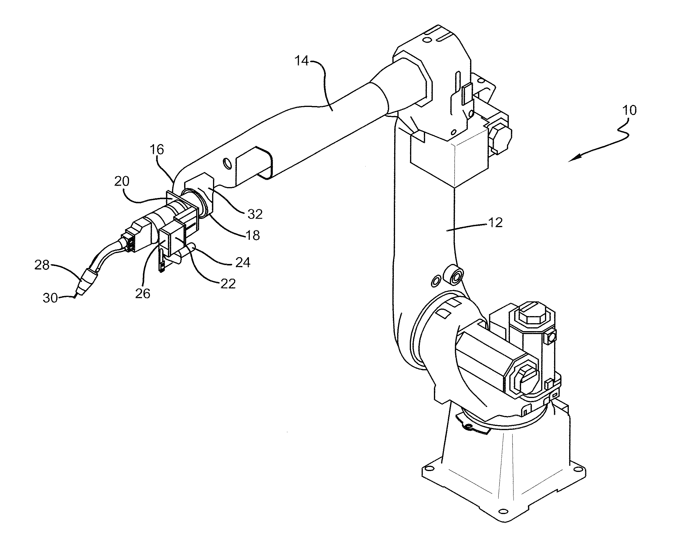
[0019]Referring now to the drawings wherein the showings are for purposes of illustrating embodiments of the invention only and not for purposes of limiting the same, FIG. 1 shows robotic welding apparatus 10. This welding apparatus will have a least a first 12 and a second 14 arm, with welding nozzle 28 affixed to the distal end of second arm 14. Positioned rearward of distal end of the second arm is laser mounting bracket 20, illustrated in the figure as transversely positioned about a longitudinal axis of second arm 14 through aperture opening in mounting bracket 20. Affixed to inwardly projecting leg of the mounting bracket is bracket leg 32 positioned essentially parallel to the longitudinal axis of second welding arm 14.

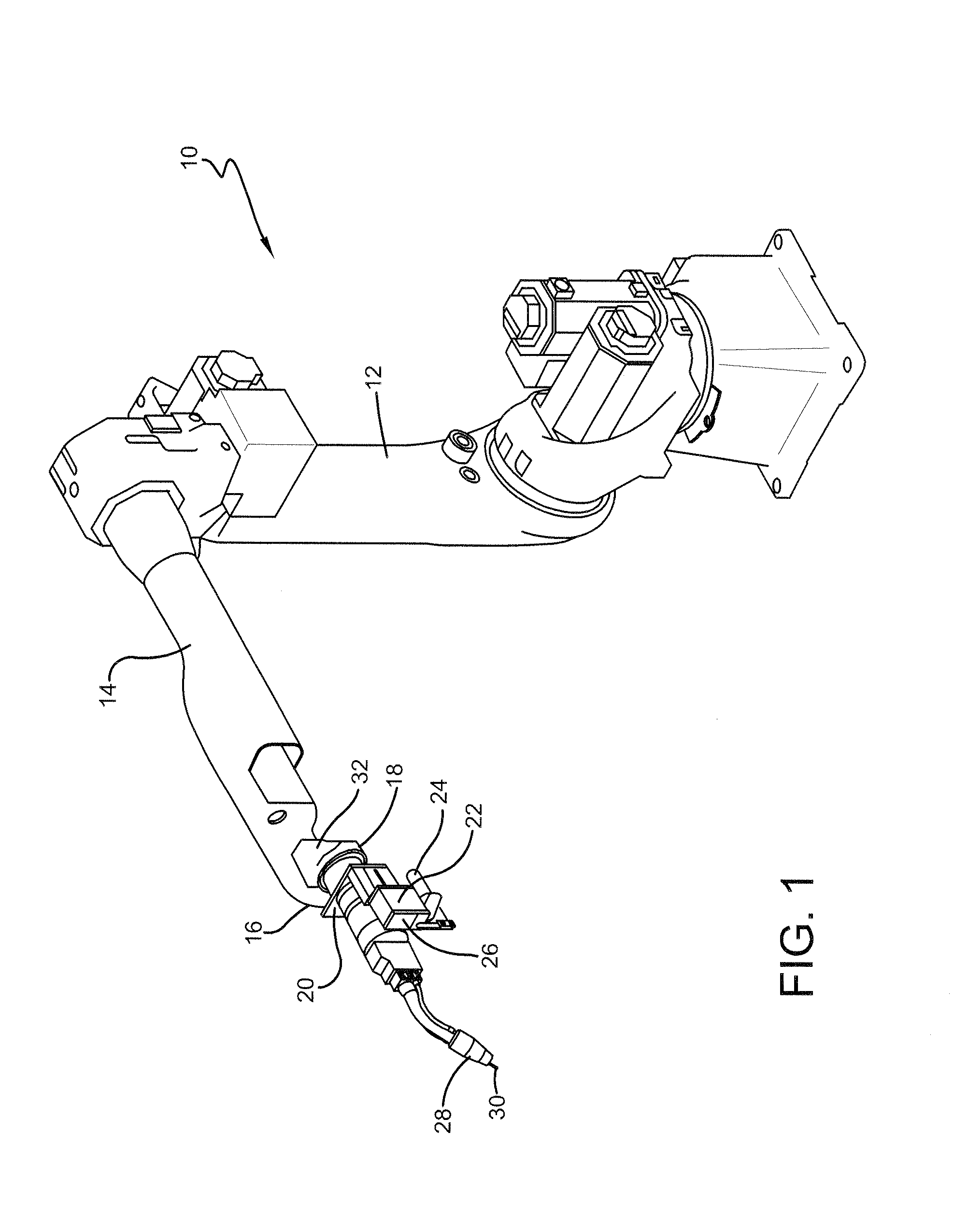
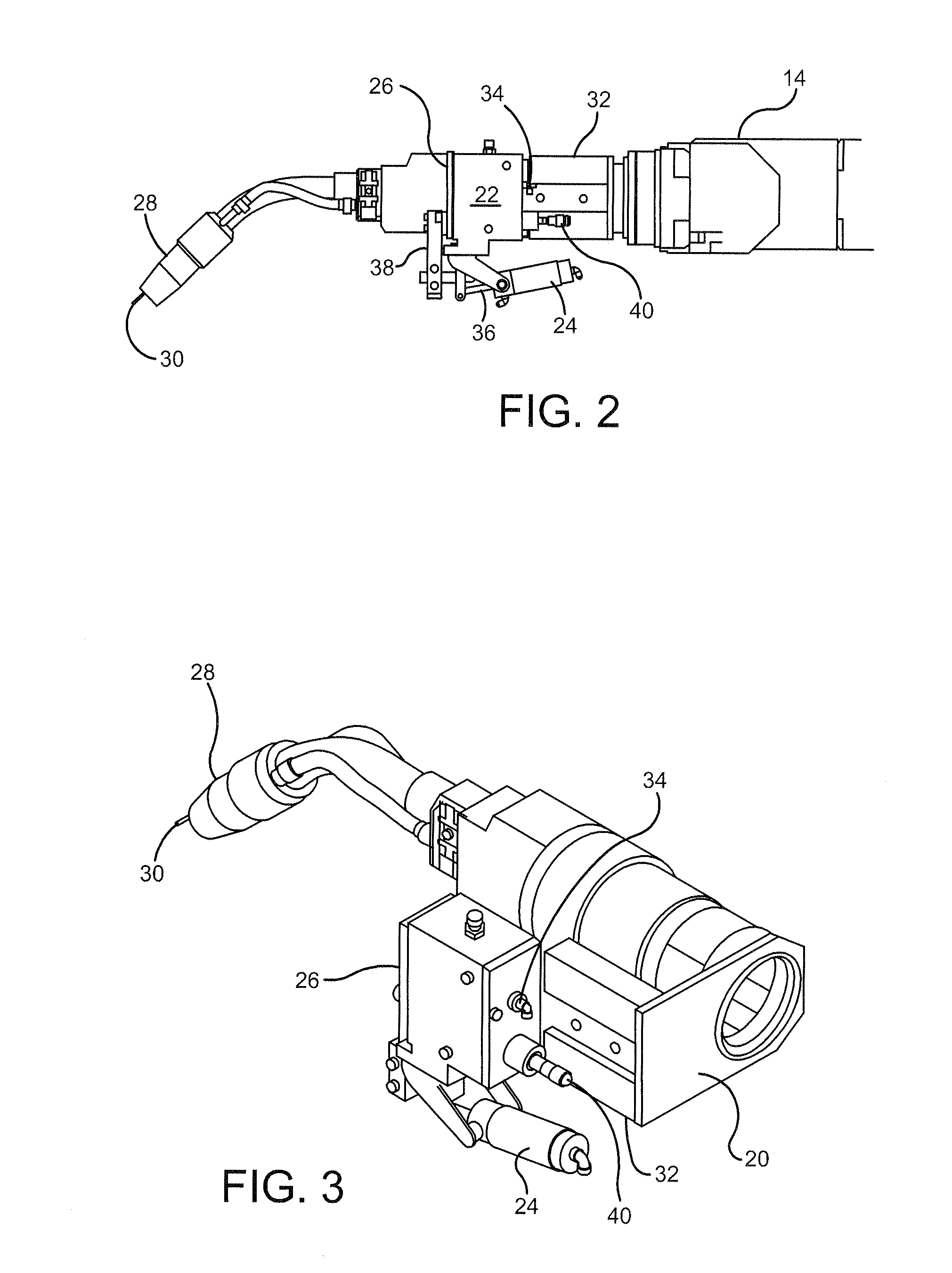
[0020]As better illustrated in FIGS. 2 & 3, bracket leg 32 is affixed to the rear of essentially rectangular housing 22, the housing having inlet 40 for cables specific to the operation of a laser unit positioned within housing 22 and inlet 34 for gaseous acces...


PUM

PropertyMeasurementUnit
Flow rateaaaaaaaaaa

Abstract

The present invention is an enclosure for a laser, the enclosure having positive pressure in the line to generate a positive gas flow within the enclosure so as to keep welding fumes, welding spatter and other contaminants off a laser beam lens.

Description

CROSS-REFERENCE TO RELATED APPLICATIONS[0001]This invention claims priority to, is a continuation-in-part application thereof, and fully incorporates by reference, U.S. Provisional Patent Application Ser. No. 61 / 900,436 filed on 6 Nov. 2013.TECHNICAL FIELD[0002]The present invention pertains to an enclosure for a laser, the enclosure having positive pressure in the line to generate a positive gas flow within the enclosure so as to keep welding fumes, welding spatter and other contaminants off a laser beam lens.BACKGROUND OF THE INVENTION[0003]Laser distance measuring can be employed in robotic welding operations. Employing a laser permits accurate determination of the location of a weld seam between two surfaces. In operation, a laser light is emitted and impinges upon one surface, then the other surface, to find the exact intersecting weld seam.[0004]In the past, this location was performed by using the wire stick out from the welding torch, to touch sense each surface, in finding ...

Claims


Application Information

Patent Timeline
IPC IPC(8): B23K9/32G01C3/00B23K9/12B23K9/095
CPCB23K9/322B23K9/0956B23K9/126G01C3/00B23K9/328B23K9/1274
Inventor PATTON, JR., DONALD M.LEE, JUNG HWAGIBSON, CRAIG A.
Owner LINCOLN GLOBAL INC
Why Eureka
Try Eureka