RF pulses for magnetic resonance

a magnetic resonance and pulse technology, applied in the field of magnetic resonance imaging and magnetic resonance spectroscopy, can solve the problems of data being affected by signal dropout, particular problems such as signal dropout, and being unable to accurately be used, so as to and improve the detectability of an mr signal

Inactive Publication Date: 2015-05-07
KINGS COLLEGE LONDON
View PDF3 Cites 9 Cited by
  • Summary
  • Abstract
  • Description
  • Claims
  • Application Information

AI Technical Summary

Benefits of technology

[0027]A second aspect of the present invention provides a method of performing an MR scan, comprising defining a cost function, C, in dependence at least on a determined range of magnetic susceptibility gradients, Gzs,min<Gzs<Gzs,max, of an object to be scanned, a quadratic phase variation, a, of a transverse magnetic field induced by an RF pulse, and a plurality of parameters defining a slice selection gradient, Gz, and a slice refocusing gradient, Gz,ref. The method further comprises determining a value of the quadratic phase variation, a, and values for the plurality of parameters defining the slice selection gradient, Gz, and the slice refocusing gradient, Gz,ref, such that the cost function, C, is maximised, and performing an MR scan using the determined values as parameters to improve the detectability of an MR signal over the determined range of magnetic susceptibility gradients.
[0028]A third aspect of the present invention provides an apparatus for calculating parameters to be used in an MR scan, comprising a processor, and a computer readable medium, the computer readable medium storing one or more instruction(s) arranged such that when executed the processor is caused to define a cost function, C, in dependence at least on a determined range of magnetic susceptibility gradients, Gzs,min<Gzs<Gzs,max, of an object to be scanned, a quadratic phase variation, a, of a transverse magnetic field induced by an RF pulse, and a plurality of parameters defining a slice selection gradient, Gz, and a slice refocusing gradient, Gz,ref. The processor is further caused to determine a value of the phase variation, a, and values for the plurality of parameters defining the slice selection gradient, Gz, and the slice refocusing gradient, Gz,ref, such that the cost function is maximised, wherein the determined values, when used as parameters of an MR scan, improve the detectability of an MR signal over the determined range of magnetic susceptibility gradients.
[0029]A fourth aspect of the present invention provides an MR scanner comprising a processor, the processor being arranged to define a cost function, C, wherein the cost function is defined in dependence at least on a determined range of magnetic susceptibility gradients, Gzs,min<Gzs−Gzs,min, of an object to be scanned, a quadratic phase variation, a, of a transverse, magnetic field induced by an RF pulse, and a plurality of parameters defining a slice selection gradient, G and a slice refocusing gradient, Gz,ref. The processor is further caused to determine a value of the phase variation, a, and values for the plurality of parameters defining the slice selection gradient, Gz, and the slice refocusing gradient, Gz,ref, such that the cost function, C, is maximised, wherein the determined values, when used as parameters of an MR scan, improve the detectability of an MR signal over the determined range of magnetic susceptibility gradients.

Problems solved by technology

If the static magnetic field is spatially inhomogeneous, the resulting data can suffer from signal dropout.
Signal dropout is a particular problem for data acquired with gradient-echo and asymmetric spin-echo techniques.
This is not achievable in practice and as such their model is inaccurate and therefore cannot be used to accurately determine the degree of quadratic phase variation, a, that the RF pulse needs to induce to reduce signal dropout from a particular range of susceptibility gradients.
It should be noted however that they found large discrepancies between the signal recovery found experimentally and that predicted theoretically by the model of Cho et al, reinforcing the claim made above that the model of Cho et al. is inaccurate and therefore should not be used to determine the optimal degree of quadratic phase variation, a. Again, Chung et al. did not specify how the RF pulse they used could be produced in practice.

Method used


Image

  • RF pulses for magnetic resonance
  • RF pulses for magnetic resonance
  • RF pulses for magnetic resonance

Examples


Embodiment Construction

Overview

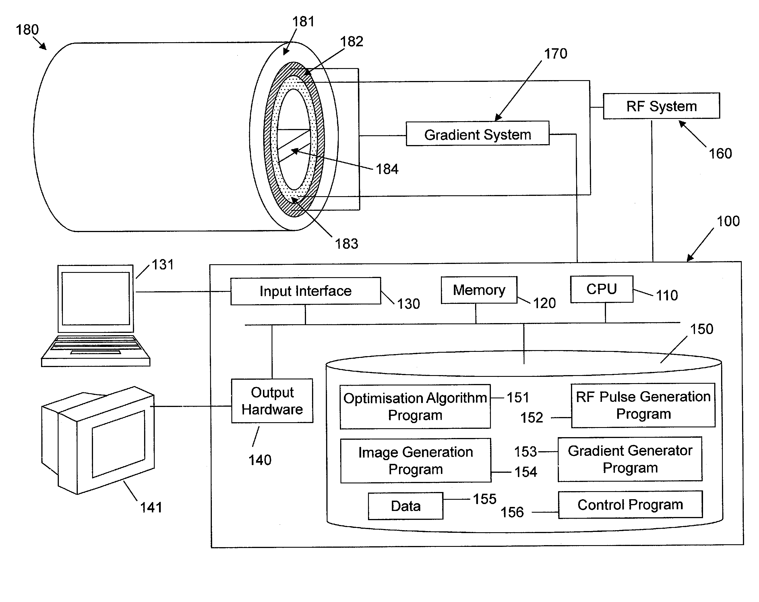
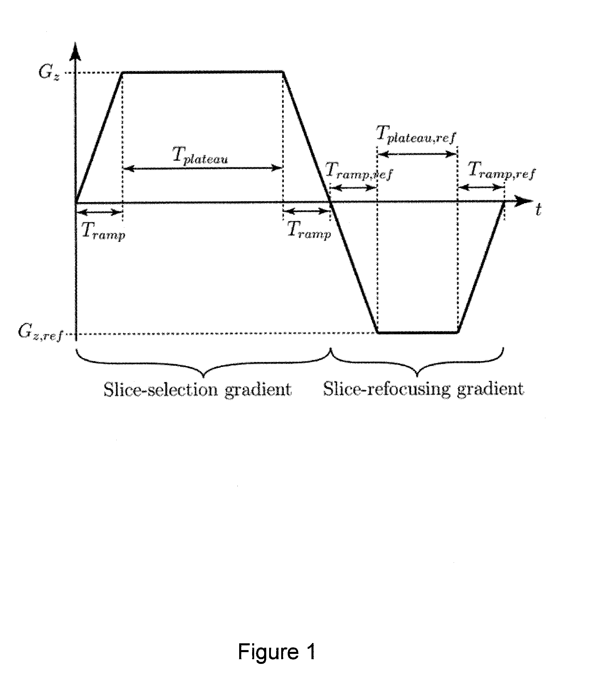
[0041]The present invention provides an algorithm that determines the optimal parameters of an RF pulse that is to be applied to the RF coil of an MRI or MRS scanner, wherein the RF pulse is optimised for a specific object upon which the MRI or MRS scan is to be performed. Additionally, in the process of finding the optimised parameters of the RF pulse, the algorithm also determines the slice selection and slice refocusing gradients that correspond to the parameters of the RF pulse and that are to be applied to the gradient coils of the MRI or MRS scanner. The main objective of this algorithm is to reduce the problem of signal dropout caused by varying linear susceptibility gradient which are present in objects. The algorithm is able to determine the optimal parameters of the RF pulse and the accompanying slice selection and slice refocusing gradients which will reduce signal dropout caused by the range of magnetic susceptibility gradient present in a specific object.

[0042]T...


PUM


Abstract

The present invention provides a method and system to reduce the problem of signal dropout in data acquired using gradient-echo and asymmetric spin-echo magnetic resonance techniques, caused by linear susceptibility gradients in the direction of slice-selection. Specifically an algorithm is used to determine the optimal parameters of a tailored radiofrequency pulse along with the accompanying slice-selection and slice-refocusing gradients to correct this signal dropout.

Description

CROSS REFERENCE TO RELATED APPLICATION[0001]This application claims priority under 35 USC 119(e) from U.S. provisional patent application No. 61 / 900,557 filed 6 Nov. 2013, the entire contents of which are incorporated herein by reference.TECHNICAL FIELD[0002]The present invention relates to the field of Magnetic Resonance Imaging (MRI) and Magnetic Resonance Spectroscopy (MRS). In particular, it relates to a method and system for designing a radiofrequency pulse along with the accompanying slice-selection and slice-refocusing gradients to reduce signal dropout in data acquired using gradient-echo or asymmetric spin-echo Magnetic Resonance (MR) techniques in regions of varying magnetic susceptibility.BACKGROUND TO THE INVENTION AND PRIOR ART[0003]Nuclear magnetic resonance is observed in materials containing nuclei with non-zero spin angular momentum. Associated with their spin angular momentum, S, these nuclei possess a magnetic dipole moment, μ. In a static magnetic field, B0, thes...

Claims


Application Information

Patent Timeline
Patent Type & Authority Applications(United States)
IPC IPC(8): G01R33/36G01R33/54G01R33/483G01R33/46
CPCG01R33/3671G01R33/483G01R33/546G01R33/46G01R33/56536G01R33/4833
Inventor WASTLING, STEPHEN JAMESBARKER, GARETH JOHN
Owner KINGS COLLEGE LONDON
Why Eureka
Try Eureka