Battery electrode materials

a battery electrode and material technology, applied in the field of battery electrode materials and batteries, can solve the problems of limiting capacity, high rate charging and/or discharging is generally very detrimental to stability, and is simply not possible at a given capacity and charge and/or discharge ra

Inactive Publication Date: 2015-05-07
NANO NOUV
View PDF1 Cites 16 Cited by
  • Summary
  • Abstract
  • Description
  • Claims
  • Application Information

AI Technical Summary

Benefits of technology

[0009]The inventors have discovered electrode materials that can deliver surprising combinations of capacity, high rates of charging and / or discharging, high depths of discharge, high power and high cycling stability.

Problems solved by technology

However high rate charging and / or discharging is generally very detrimental to stability.
DOD may need to be severely limited to provide sufficient cycling stability at high rates, effectively limiting capacity.
Alternatively, long lifetimes are simply not possible at a given capacity and charge and / or discharge rate.

Method used


Image

  • Battery electrode materials
  • Battery electrode materials
  • Battery electrode materials

Examples


example 1

[0105]Nickel (Ni) was coated on a 0.45 μm cellulose acetate filter membrane using electroless deposition. The surface area of this substrate is estimated at ˜2.3 m2 / cc. The volume fraction of polymer is about 34%. The membrane was coated with a seed layer prior to electroless deposition. Weight measurements showed that the average thickness of the Ni coating was about 70 nm.

[0106]This sample was mounted in a flooded cell with a metal hydride counter electrode and an aqueous electrolyte with 6M potassium hydroxide and 1 wt % lithium hydroxide.

[0107]The material was activated using a conventional procedure by cycling at 0.2 C. After 3 cycles the capacity was ˜67.5 mAh / cc.

[0108]The material was further activated by cycling at higher rates. After 8 cycles at 5 C, the capacity was ˜234 mAh / cc. After further 6 cycles at 10 C, the capacity was ˜245 mAh / cc. After further 4 cycles at 20 C, the capacity was 249.7 mAh / cc. After a further 20 cycles at 10 C, the capacity was 270 mAh / cc. After a ...

example 2

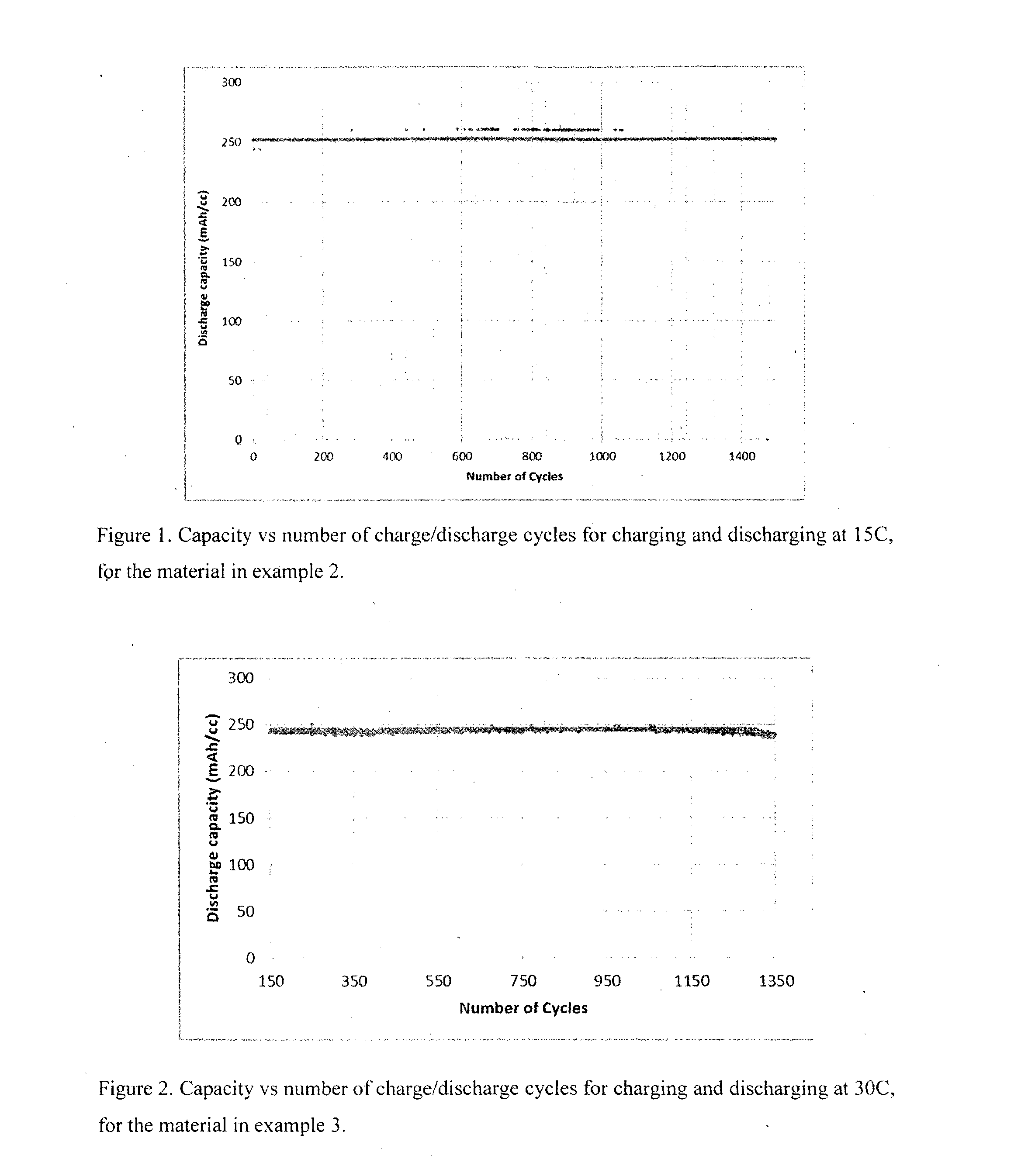
[0111]Material was prepared in a similar manner to Example 1. The estimated thickness of nickel was 58 nm. The sample was initially activated by 11 cycles at 5 C, to give a discharge capacity of ˜189 mAh / cc. The sample was further activated by 11 cycles at 10 C to give a discharge capacity of ˜221 mAh / cc, then 10 cycles at 15 C to give a discharge capacity of ˜228 mAh / cc, then a further 30 cycles at 15 C to give a discharge capacity of ˜252 mAh / cc. The gravimetric discharge capacity was estimated as ˜143 mAh / g. The material was then cycled at 15 C at ˜100% DOD. FIG. 1 shows the capacity vs number of cycles at 15 C. Clearly the material is stable at 15 C. Discharging at 15 C gives power densities of ˜3.8 W / cc and ˜2.1 W / g, calculated using an average discharge voltage of 1V.

example 3

[0112]Material was prepared a similar manner to Example 1. The nickel thickness was estimated at 70 nm. The sample was initially activated at 5 C. After the 10th cycle the discharge capacity was 231 mAh / cc. The gravimetric discharge capacity was estimated as ˜118 mAh / g. FIG. 2 shows the capacity vs number of cycles at 30 C. Clearly the material is stable at 30 C. Discharging at 30 C gives power densities of ˜7 W / cc and ˜3.5 W / g, calculated using an average discharge voltage of 1V.


PUM

PropertyMeasurementUnit
volume fractionaaaaaaaaaa
thicknessaaaaaaaaaa
volume fractionaaaaaaaaaa

Abstract

An electrode material for a battery or for a capacitor, supercapacitor or a pseudo capacitor comprises a porous substrate coated with a coating comprising a conducting material and an active material, wherein the thickness of the coating is less than 1 micrometre and the volume fraction of active material is greater than 5%. In another aspect, the electrode material comprises a metallic network structure and an active material connected to the metallic structure, wherein the calculated volume fraction of active material is greater than 5%, and the surface area of the material is greater than 5 m2 / g.

Description

FIELD OF THE INVENTION[0001]The present invention relates to novel battery electrode materials and batteries using same. In one aspect the invention relates to nickel-based electrode materials and batteries using same.BACKGROUND TO THE INVENTION[0002]Considerable demand exists for technology that can significantly improve battery performance. There are several aspects of battery performance that may be important for a given application. For example, the rate at which the battery may be charged determines how long it takes to fully charge the battery. The rate at which the battery may be discharged is critical to how much power the battery can deliver. The amount of energy stored in the battery per unit weight, or the amount of energy stored in the battery per unit volume, may also be important. Power may also be expressed per unit weight or per unit volume. These properties may also be expressed per unit area. Capacity is often used to indicate the amount of charge stored and availa...

Claims


Application Information

Patent Timeline
Patent Type & Authority Applications(United States)
IPC IPC(8): H01M4/02H01M4/38
CPCH01M4/02H01M2004/021H01M4/38H01M4/0445H01M4/045H01M4/661H01M4/668H01M4/806H01M10/345H01M4/505H01M4/52H01M4/525H01M4/5825H01M4/48Y02E60/10Y02E60/13H01M4/36H01M4/62H01M4/80H01M4/66H01M4/58H01G11/24
Inventor EDWARDS, GEOFFREY ALANGEORGE, PETER ANTHONYSONG, QUANSHENG
Owner NANO NOUV
Why Eureka
Try Eureka