Microcellular communications antenna and associated methods

a micro-cellular and antenna technology, applied in the field of communication, can solve the problems of unreachable spaces, inability to realize a strip-shaped coverage cell, and inconvenient operation

Active Publication Date: 2015-05-14
HARRIS CORP
View PDF20 Cites 251 Cited by
  • Summary
  • Abstract
  • Description
  • Claims
  • Application Information

AI Technical Summary

Benefits of technology

[0010]In view of the foregoing background, it is therefore an object of the present invention

Problems solved by technology

Additionally, the resulting cell would not be rectangular, but triangular shaped and the signal strength not uniform.
Other problems with towers include unreachable spaces (building interiors, tunnels, backside of hills), cannot realize a strip shaped coverage cell, will not provide road only coverage, cells cannot follow a turn in a road, limited frequency reu

Method used


Image

  • Microcellular communications antenna and associated methods
  • Microcellular communications antenna and associated methods
  • Microcellular communications antenna and associated methods

Examples


Embodiment Construction

[0024]The present invention will now be described more fully hereinafter with reference to the accompanying drawings, in which preferred embodiments of the invention are shown. This invention may, however, be embodied in many different forms and should not be construed as limited to the embodiments set forth herein. Rather, these embodiments are provided so that this disclosure will be thorough and complete, and will fully convey the scope of the invention to those skilled in the art. Like numbers refer to like elements throughout.

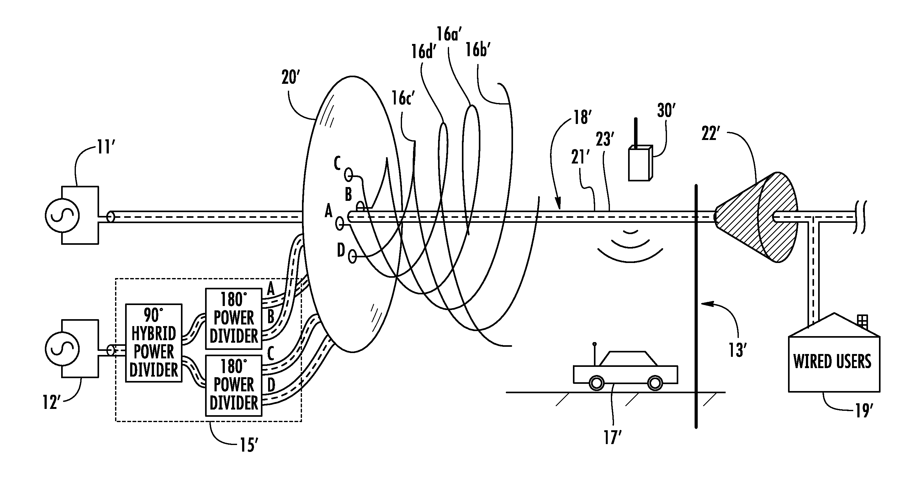
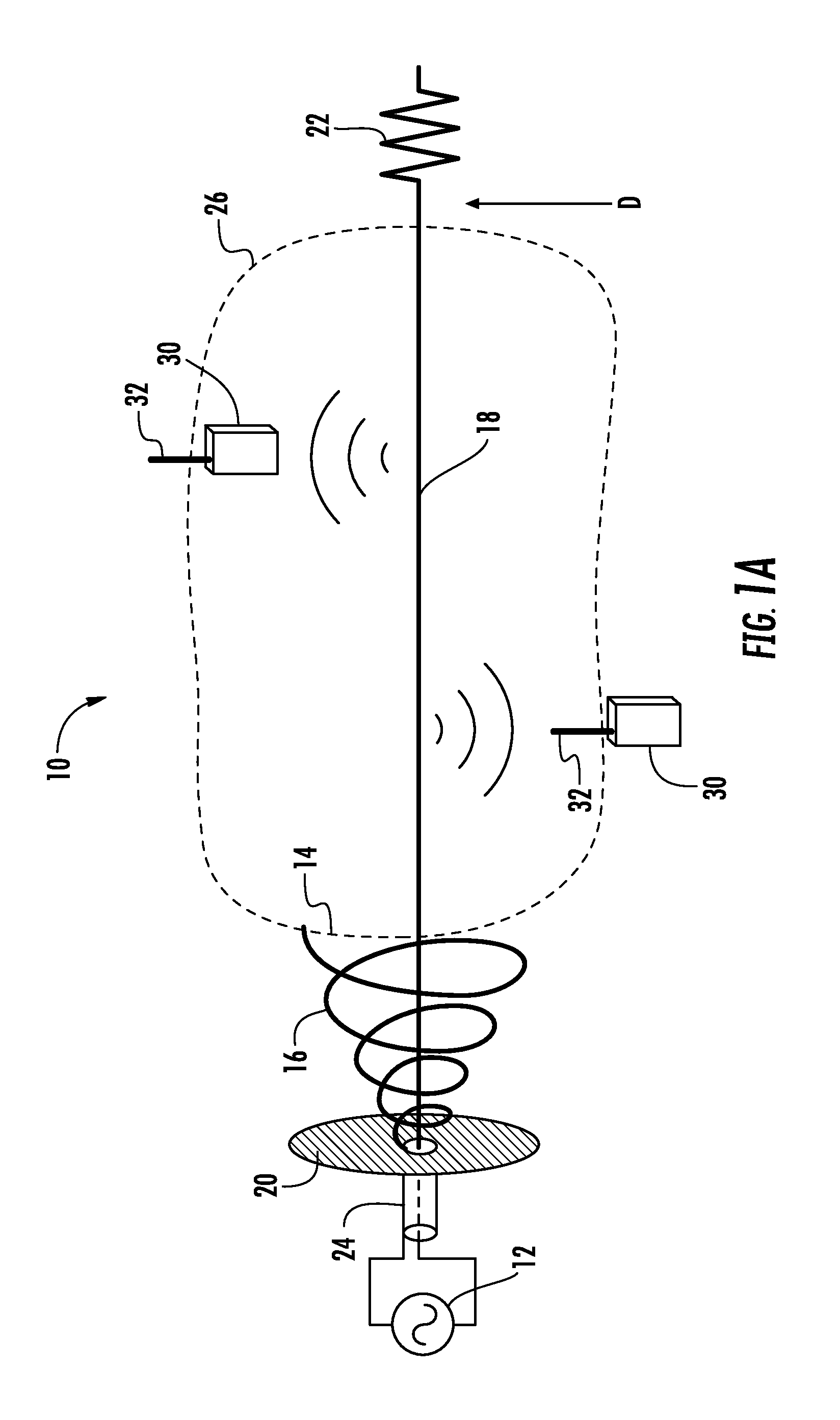
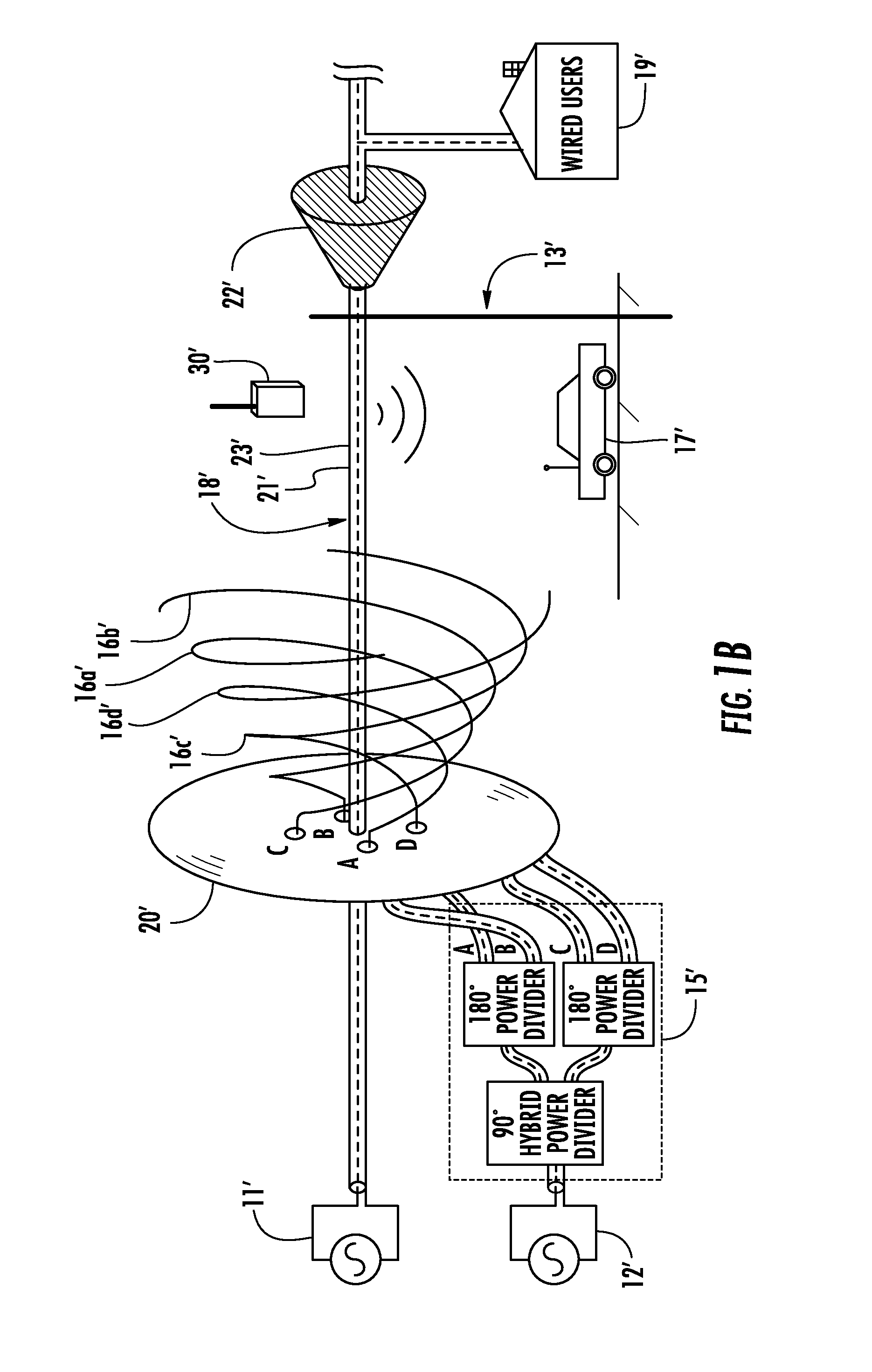
[0025]Referring initially to FIGS. 1-3, a radio frequency (RF) communications system 10 in accordance with the present embodiments will be described. The RF communications system 10 includes a local RF communications device 12 and an RF antenna 14 including a conical RF launch structure 16 coupled to the local RF communications device 12, and an elongate electrical conductor 18 having a proximal end P coupled to the conical RF launch structure 16 and a dis...


PUM


Abstract

A radio frequency (RF) communications system includes a local RF communications device and an RF antenna including a conical RF launch structure coupled to the local RF communications device, and an elongate electrical conductor having a proximal end coupled to the conical RF launch structure and a distal end spaced apart from the conical RF launch structure to define an elongate RF coverage pattern. The elongate conductor may be a coaxial cable. At least one remote RF communications device, within the elongate RF coverage pattern, wirelessly communicates with the local RF communications device.

Description

FIELD OF THE INVENTION[0001]The present invention relates to the field of communications and, more particularly, to wireless communications and related methods.BACKGROUND OF THE INVENTION[0002]Current cell towers provide free space radiation and directional antenna sectors. The required narrow antenna beams to cover only a highway cannot be realized at 698 to 2700 MHz cellular frequencies. For example, for a 10 mile long by 100 foot wide highway coverage cell, the beamwidth required is tan−1 (100 / 52800)=0.11 degrees, which may require a 65 dBi gain antenna hundreds of wavelengths diameter. Additionally, the resulting cell would not be rectangular, but triangular shaped and the signal strength not uniform. Other problems with towers include unreachable spaces (building interiors, tunnels, backside of hills), cannot realize a strip shaped coverage cell, will not provide road only coverage, cells cannot follow a turn in a road, limited frequency reuse, low security and too far for self...

Claims


Application Information

Patent Timeline
IPC IPC(8): H01Q13/26H01Q13/28
CPCH01Q13/28H01Q13/26H01P3/10H01Q1/46H01Q11/083
Inventor PARSCHE, FRANCIS EUGENE
Owner HARRIS CORP
Why Eureka
Try Eureka