Low power semi-reflective display

a display and low-power technology, applied in the field of low-power semi-reflective display, can solve the problems of the performance and color display precision of the current lcd display, and the battery life has become a major issue in portable electronic equipmen

Active Publication Date: 2015-05-14
NOVASOLIX
View PDF5 Cites 19 Cited by
  • Summary
  • Abstract
  • Description
  • Claims
  • Application Information

AI Technical Summary

Problems solved by technology

Battery life has become a major issue in portable electronic equipment.
Alternative technologies such as e-ink have been developed, but they have neither the performance nor color display precision on the current LCD displays.

Method used


Image

  • Low power semi-reflective display
  • Low power semi-reflective display
  • Low power semi-reflective display

Examples


Embodiment Construction

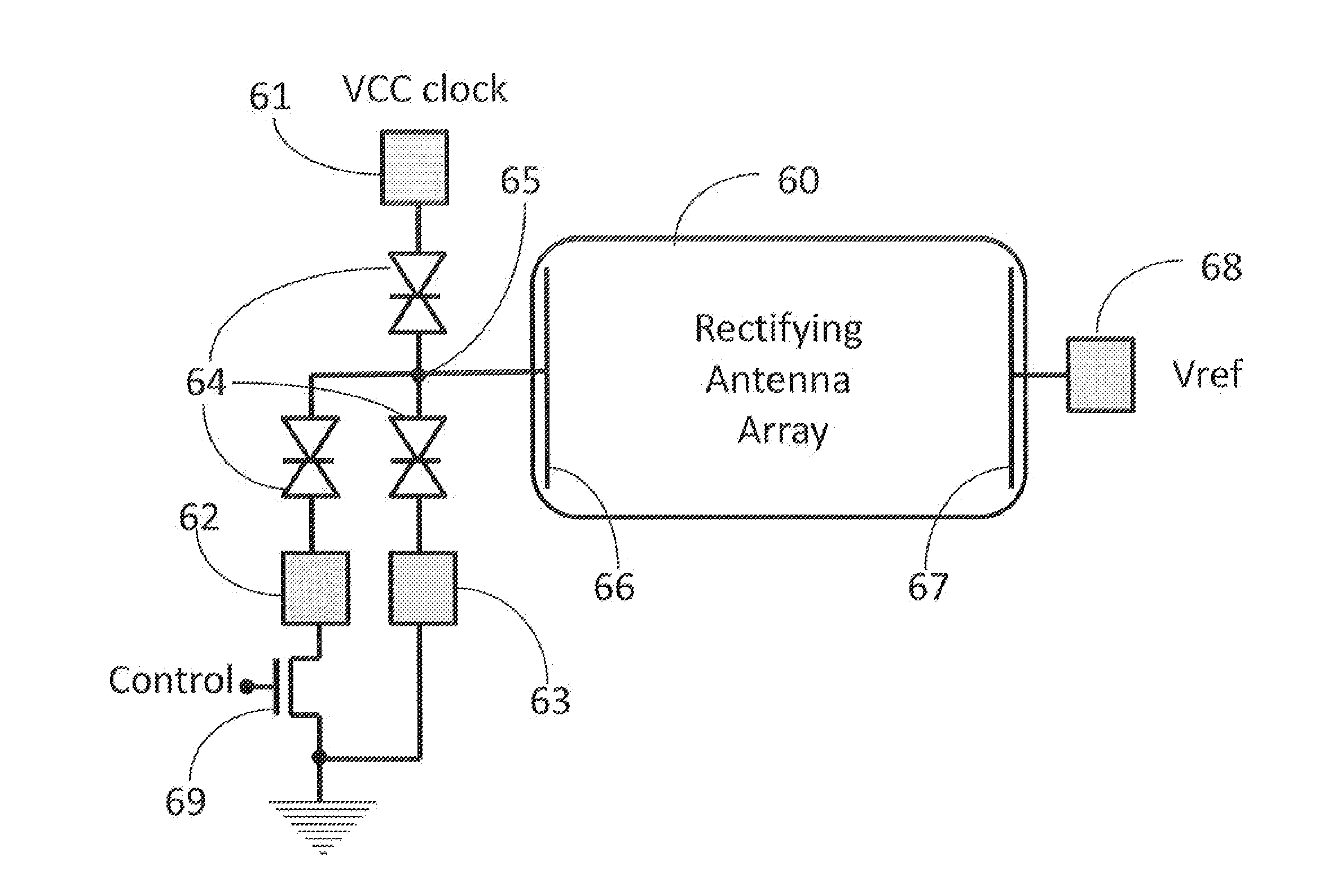
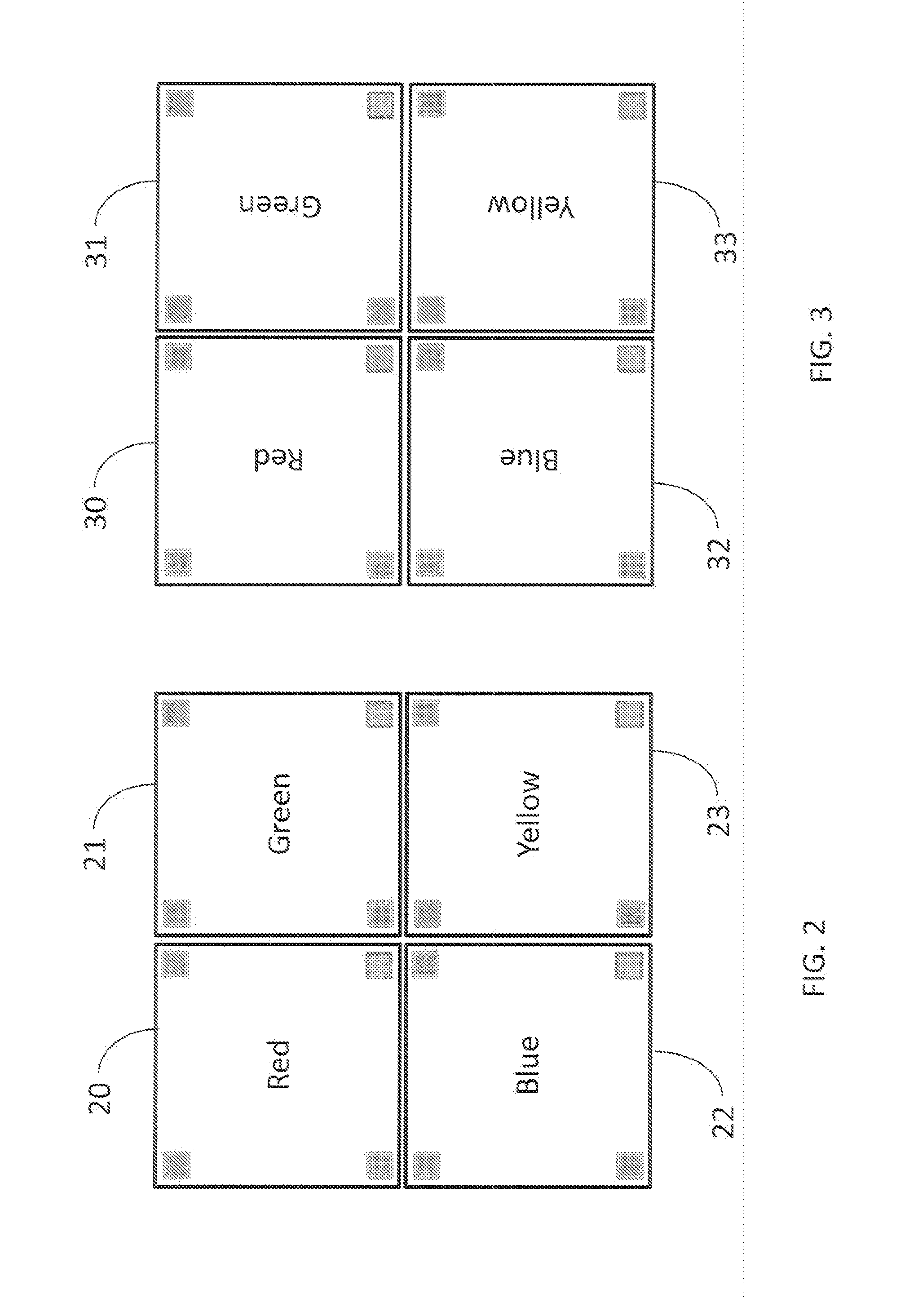
[0003]Therefore, various embodiments of the invention may relate to the manufacture and design of a low-power semi-reflective display, which may be comprised of an array of pixels, where each pixel may be further comprised of four sub-pixel sized visible light rectifying antenna arrays, each of which may be individually controlled via TFT-tunnel diode logic, comprising at least one latch, to either absorb light producing electric power or consuming electric power to amplify one of four different colors of light.

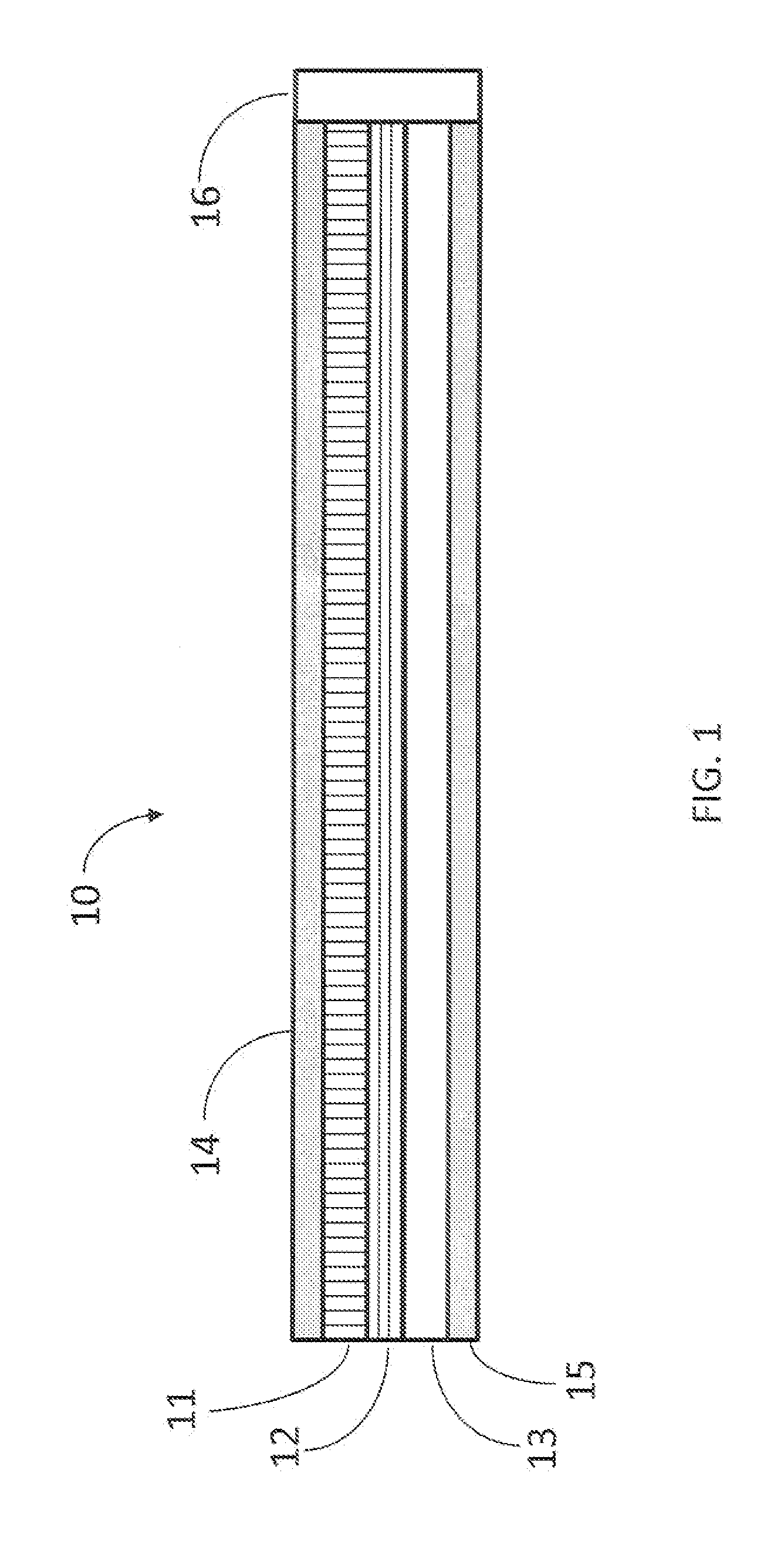
[0004]In other embodiments of the present invention, a display may be comprised of an array of sub-pixels, where each sub-pixel may be further comprised of at least two layers of arrays of collinear light frequency antenna, where the light frequency antenna in the first of the at least two layers of sub-pixels may be perpendicular to the light frequency antenna in the second of the at least two layers of sub-pixels. Furthermore, solder bumps may perform the electric coupling ...


PUM

PropertyMeasurementUnit
electric poweraaaaaaaaaa
light frequencyaaaaaaaaaa
frequenciesaaaaaaaaaa

Abstract

A semi-reflective display and a method for fabricating and assembling a semi-reflective display are presented, where the display may be comprised of visible light rectifying antenna arrays tuned to four different colors, which when forward biased may use electric power to amplify reflected colored light, and when reversed biased may generate electric power by absorbing light. TFT-tunnel diode logic may be used to control each sub-pixel.

Description

FIELD OF THE INVENTION[0001]Various embodiments of the present invention may pertain to the design and / or manufacture of a low-power semi-reflective display comprised of pixel sized visible light rectifying antenna arrays.BACKGROUND OF THE INVENTION[0002]Battery life has become a major issue in portable electronic equipment. One of the highest uses of power in such devices may be the displays. Alternative technologies such as e-ink have been developed, but they have neither the performance nor color display precision on the current LCD displays. Most of the power used in LCD displays may occur from their back lights, and yet 97% of the generated light may be absorbed by the films and filters in the display itself. Only 3% of the light actually propagates out of the display as the image seen by the viewer. It would be desirable to have a fast switching reflective display. The inventor, in U.S. patent application Ser. No. 13 / 454,155 filed Apr. 24, 2012, describes a solar array compris...

Claims


Application Information

Patent Timeline
Patent Type & Authority Applications(United States)
IPC IPC(8): G06F1/26G09G3/20G09G3/36G02F1/17G02F1/19
CPCG06F1/26G09G3/36G09G3/2003G09G2320/0626G09G2360/08G09G2360/144G09G2330/02G02F1/19G09G3/3433G09G2300/08G02B26/02H01L31/1085G02F1/17H02J7/00G06F1/32H01L27/142H01L27/156G06F1/1613G06F3/0412
Inventor COOKE, LAURENCE H.
Owner NOVASOLIX
Why Eureka
Try Eureka