
Reduced pipe wear in slurry transport pipelines

a technology of slurry transportation pipelines and pipe wear, which is applied in pipeline systems, bulk conveyors, gas/liquid distribution and storage, etc., can solve problems such as pipe wear reduction

Inactive Publication Date: 2015-05-14
SYNCRUDE CANADA LTD
View PDF16 Cites 1 Cited by
  • Summary
  • Abstract
  • Description
  • Claims
  • Application Information

AI Technical Summary

Benefits of technology

The present invention relates to a method for reducing wear and increasing the life of an oil sand slurry pipeline. It has been found that operating the pipeline at high velocities leads to erosion at the bottom of the pipe, while operating it at low velocities results in the formation of a protective bed that reduces wear and tear. The invention also includes methods for controlling pipeline blockage caused by solids accumulation, which can be detected using instrumentation. The technical effects of the invention include reduced costs, improved efficiency, and reduced risk of pipeline failure.

Problems solved by technology

However, it was surprisingly discovered that operating the slurry transportation pipeline near or below the deposition velocity (i.e., at stationary bed conditions) resulted in decreased wear of the pipe due to the formation of a protective stationary bed at the 6 o'clock position of the pipe.

Method used


Image

  • Reduced pipe wear in slurry transport pipelines
  • Reduced pipe wear in slurry transport pipelines
  • Reduced pipe wear in slurry transport pipelines

Examples


example 1

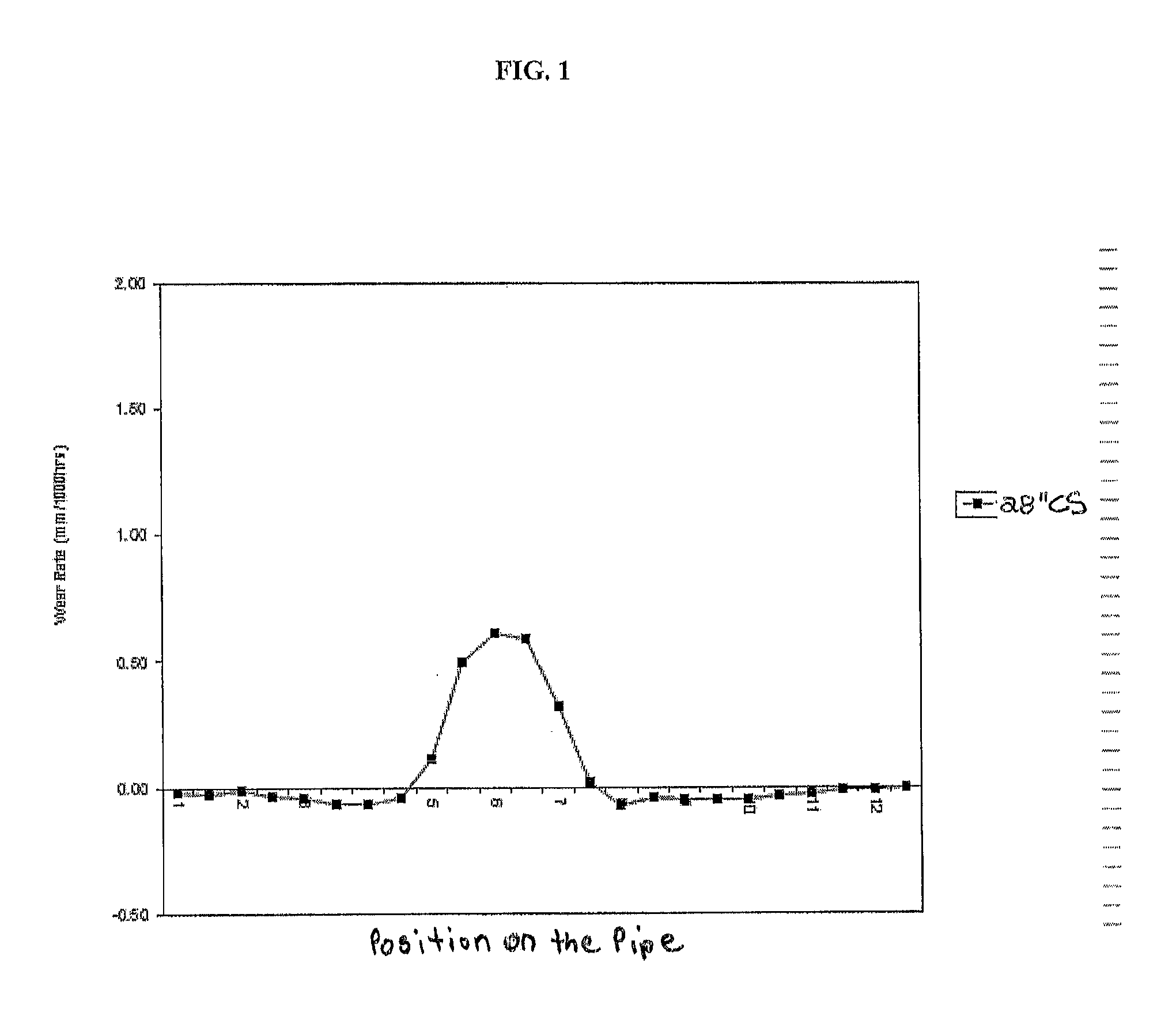
[0035]Routinely, piping used by the applicant in coarse tailings pipelines is 24″ in diameter (inner diameter). However, recently, some of the 24″ pipe of Coarse Tailings Pipeline 1 was replaced with 28″ pipe, as there was a need to increase the length of this pipeline and the already-installed pumping capacity was not in place to use 24″ pipes for this extension. Since the pipeline pressure drop is known to decrease with pipe diameter, a section of 24″ diameter piping was replaced with 28″ diameter piping.

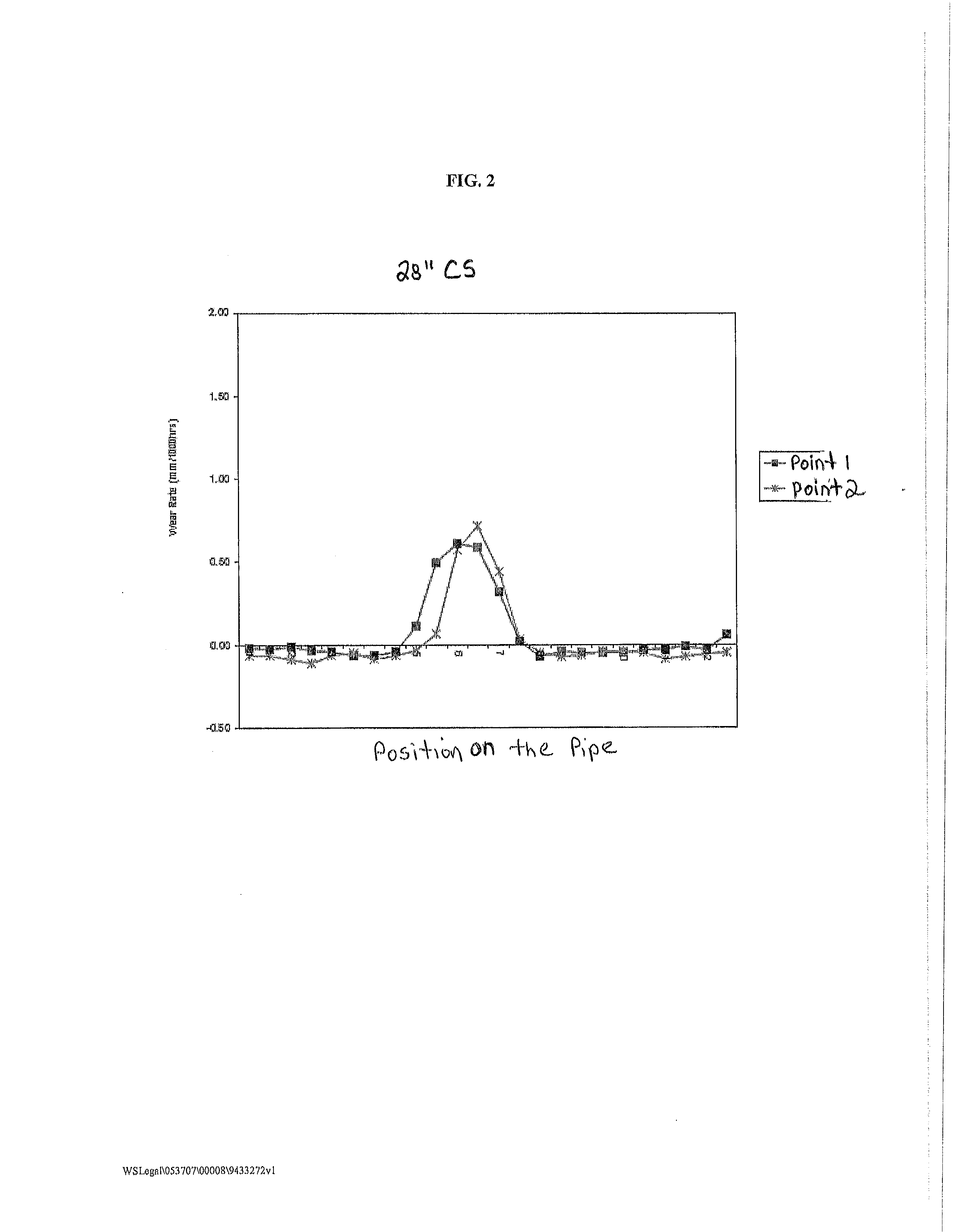
[0036]However, it was surprisingly discovered that the 28 inch lines showed significant wear rate reductions as compared to 24 inch lines. Further, it appeared as though a stationary bed had formed on the pipe bottom and that the stationary bed was acting as a protective layer to the steel.

[0037]FIG. 4 shows the wear rate (mm / 1000 hrs) results obtained when testing Coarse Tailings Pipeline 1 for wear at two points along the pipeline where there was 24″ SS pipe (dark solid squares ...

example 2

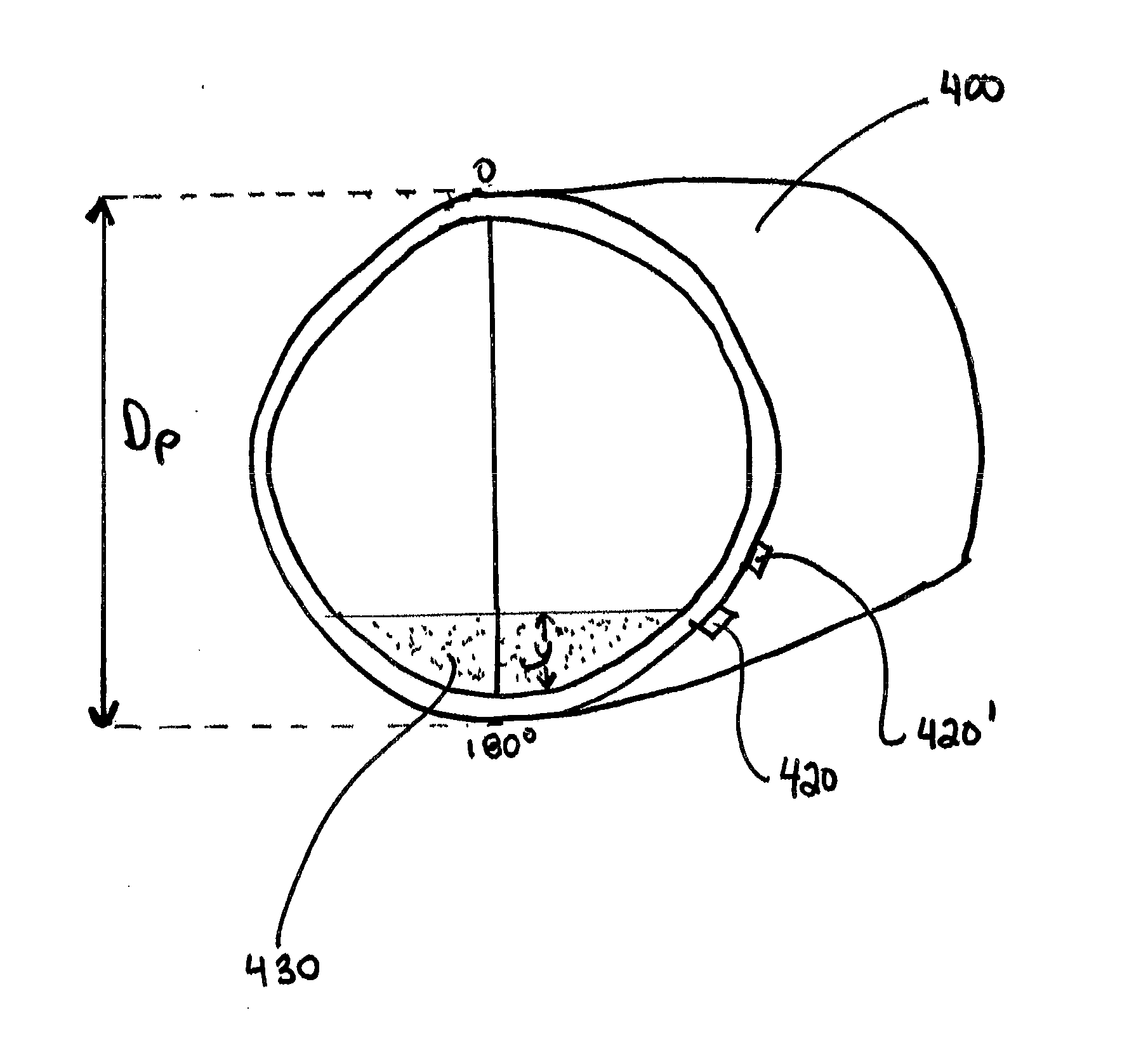
[0044]FIG. 9 is an illustration of a pipe 400 having a pipe diameter (Dp) where two densitometers, 420 and 420′, have been placed at about the 155° and 130° position of the pipe 400, respectively. In this example, “y”, which is the height of the stationary bed of solids 430, is 5 cm, and Dp is 1 meter. Thus, the relative stationary bed height, y / Dp, is about 0.05, which was found to be around the minimum relative height for the stationary bed for reduced pipe wear at the 6 o'clock position (i.e., 180° position) of the pipe 400. Densitometer 420 is positioned to be able to detect the minimum relative height of 0.05.

[0045]It was found, however, that if the relative bed height is too high, i.e., approaches 0.25, while the wear at the 6 o'clock position of the pipe is still reduced, wear at the 4 o'clock (i.e., 120° position) and 8 o'clock position (i.e., 240° position of the pipe) begins to increase. This is believed to be due to the disturbance / movement of the surface of the bed at th...


PUM


Abstract

A process for operating a settling slurry transportation pipeline is provided, comprising: determining the deposition velocity for a particular slurry being transported through the pipeline; and operating the pipeline at an operating velocity at or near the deposition velocity to form a stationary or near stationary bed of solids that will still allow the slurry to freely flow through the pipeline and not plug the pipeline.

Description

FIELD OF THE INVENTION[0001]The present invention relates to a process for reducing pipe wear in slurry transport pipelines by operating the pipeline at a velocity that produces a stationary or near stationary solids bed at the bottom of the pipe.BACKGROUND OF THE INVENTION[0002]The wear on slurry transportation pipelines within the oil sand industry is a major driver of both downtime and capital expenditure. Oil sand slurries are reasonably concentrated (>35% solids by volume), typically having a sand particle diameter between 0.18 and 0.3 mm and rocks and lumps to about 125 mm, which are transported at reasonably high velocities (3 to 5.5 m / s), In an oil sand mining operation, there are a number of pipelines which contain settling slurries. An example of two major slurry pipeline systems, among others which exist in an oil sand mining and extraction operation, are oil sand hydrotransport pipelines, which carry concentrated slurries of oil sand and water from the mine to the ext...

Claims


Application Information

Patent Timeline
IPC IPC(8): B65G53/30
CPCB65G53/30F17D1/088F17D3/01
Inventor REVEGA, TIMCHIOVELLI, STEFANOREID, KEVIN
Owner SYNCRUDE CANADA LTD
Learn More