
Predictive temperature management system controller

Inactive Publication Date: 2015-05-14
PASSIVSYST
View PDF11 Cites 45 Cited by
  • Summary
  • Abstract
  • Description
  • Claims
  • Application Information

AI Technical Summary

Benefits of technology

The present invention provides a controller for a temperature management system that takes into account the cost of maintaining room temperature and the effect of scheduling and energy input. The control is based on a criterion that aims to minimize the amount of energy consumed while ensuring the room temperature is maintained within acceptable limits. The controller takes into account the effect of energy input in a given control period on room temperature in subsequent periods. The control system can be algorithmic or modulated based on operational constraints, and may include a boiler that is controlled by a pulse code modulated signal. The technical effect of the invention is to optimize energy usage and minimize costs while controlling room temperature.

Problems solved by technology

Consequently, this known method of control can fail to achieve energy efficiency and / or the best comfort for the occupants of the house.
For example, the room temperature is prone to fluctuate significantly under thermostatic control and can be uncomfortably low for the first part of a period with a raised set point temperature.
Furthermore, if the set point temperature is raised for a relatively short period of time, this could result in further energy wastage as the temperature of the room increases gradually over that period, only reaching the vicinity of the set point temperature towards, or after, the end of the period of the raised set point temperature.

Method used


Image

  • Predictive temperature management system controller
  • Predictive temperature management system controller
  • Predictive temperature management system controller

Examples


Embodiment Construction

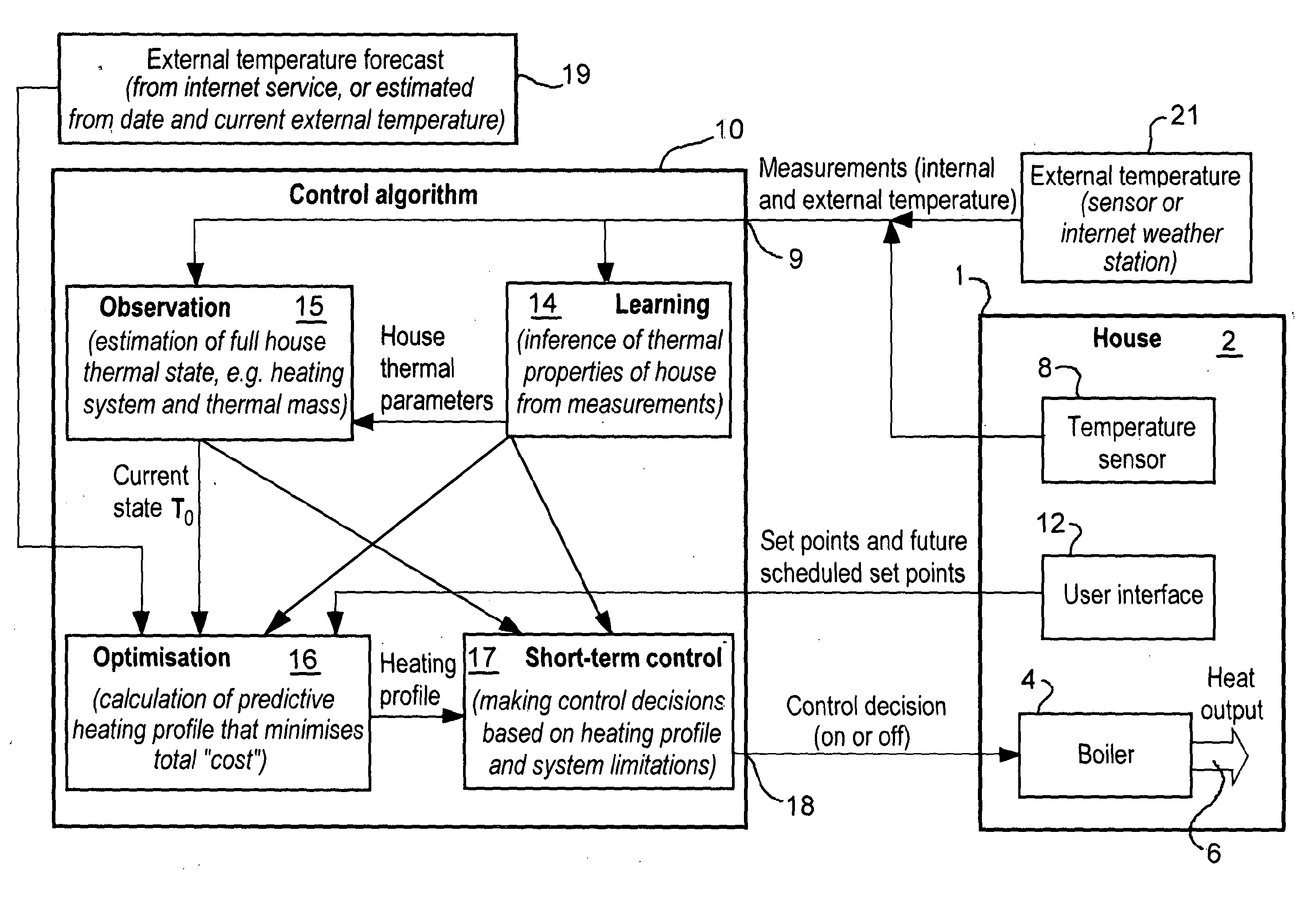
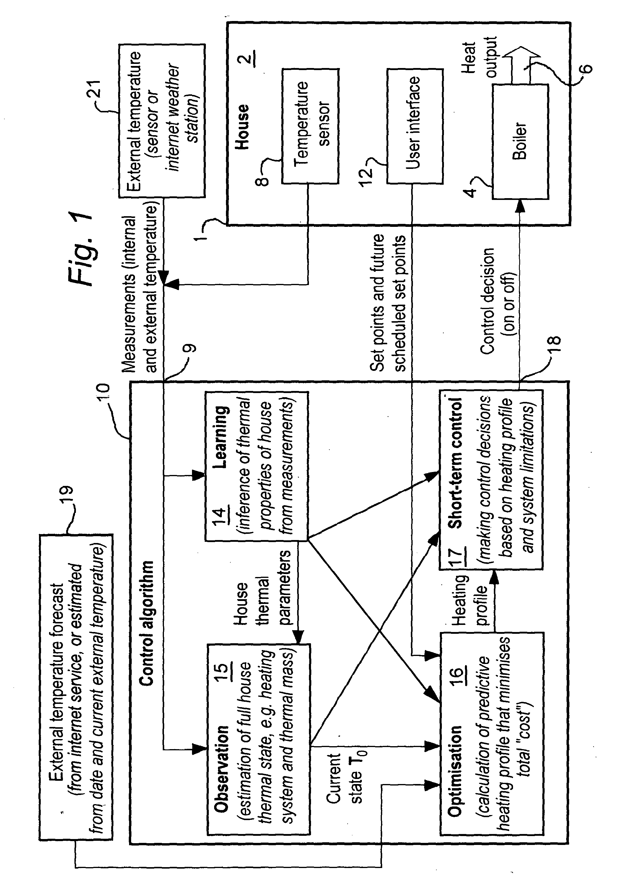
[0050]In FIG. 1, the reference numeral 1 denotes a house having one or more rooms 2 to be heated by a temperature management system comprising a boiler 4 linked to a heat delivery system 6 such as a set of radiators. Although the invention is described in relation to a boiler-based heating system, the benefits provided by the controller according to the invention are also applicable to other types of temperature management systems, in particular heat-pump based, heating and / or cooling systems.

[0051]A temperature sensor in the house (or a respective sensor in each room) is denoted by reference numeral 8 and feeds an output representative of the detected temperature to an input 9 of a controller 10 in accordance with the invention. The controller 10 also has an input for control signals from a user interface 12 within the house 1. The user interface 12 can be used by a user to set up a schedule of set point temperatures over a control period (for example, a full day) and may also enab...


PUM


Abstract

A controller for a temperature management system for heating and / or cooling a room in accordance with a schedule of set point temperatures over a control period as a data processor arrangement (10). A signal indicative of the current temperature of the room is received at a temperature input (9) for receiving a signal indicative of the current temperature in the room and a control output (18) for supplying control signals to the system. The controller has at least one electronic memory for storing said schedule of set point temperatures, a relationship, based on known heating or cooling characteristics of the room, between the energy supplied to the system in a portion of the control period and the predicted temperature of the room during that portion and subsequent portions of the control period. The electronic memory also stores a first parameter value representative of the cost of supplying said energy and a second parameter value representative of a predetermined acceptability of variations of the actual or predicted temperature of the room from the set point schedule, wherein the processor arrangement (10) is operable to calculate, for each said portion, the energy to be supplied to the system in order for a plurality of parameter values to satisfy a predetermined criterion, said plurality of parameter values comprising said first parameter value and said second parameter value.

Description

FIELD OF THE INVENTION[0001]This invention relates to a controller for a temperature management system, and to a method of controlling such a system.BACKGROUND TO THE INVENTION[0002]The invention is particularly applicable to temperature management systems, such as heating and / or air conditioning systems, that are used to control the temperature of one or more rooms in a building or other structure. The invention is more particularly, but not exclusively, concerned with domestic space heating systems and their control.[0003]Most domestic space heating systems control the temperature by targeting a set point temperature (which may form part of a schedule of set point temperatures that vary over a control period) and using a thermostat with hysteresis to turn the heat source on and off. This level of control is based only on the current state of the house and its heating system, and does not take into account any forward planning or knowledge of the thermal response of the house. Cons...

Claims


Application Information

Patent Timeline
IPC IPC(8): F24F11/00G06N5/04G05B15/02
CPCF24F11/0009G06N5/04G05B15/02F24F11/30F24F2110/10F24F2130/00F24F2130/10F24F11/62F24F11/64F24F11/46F24F11/47G05D23/1923F24F11/58F24F11/63
Inventor CARTER, EDWINROBERTS, PETER
Owner PASSIVSYST
Learn More