Device and method for measuring a camera

a technology for measuring devices and cameras, applied in the field of devices and methods for measuring cameras, can solve the problems of large measurement errors, large measurement errors, and inability to accurately adjust, and achieve the effects of short testing period, fast and precisely adjustable mass, and small mass

Active Publication Date: 2015-05-21
ROBERT BOSCH GMBH
View PDF15 Cites 18 Cited by
  • Summary
  • Abstract
  • Description
  • Claims
  • Application Information

AI Technical Summary

Benefits of technology

[0015]One additional advantage of the present invention is that, in contrast to conventional systems, the loop structure of the measuring procedure may be changed, so that the collimator runs through only one single through-focus scan in an outer loop, and the adjustable first mirror unit quickly sets the respective image positions in succession in an inner loop.
[0016]One additional advantage is that when adjusting the first mirror unit, which may be designed having a small mass and is quickly and precisely adjustable, the measurement may be carried out in a shorter testing period than when pivoting large masses such as the camera or the collimator device.
[0017]In addition to the measurement of identical cameras, cameras having a different aperture angle may also be measured. For this purpose, the second mirror device is advantageously designed having different mirror sets for the cameras having different aperture angles, i.e., generally having mirror units which are farther apart for cameras having a larger aperture angle. Such a second mirror device may thus be used for different cameras without having to replace, modify, or adjust it, with only a software adjustment having to be carried out for the control signals for controlling the mirror adjustment device and / or the adjustment device of the collimator device.
[0018]In addition to measuring monocular cameras, the measurement of stereo camera systems is also possible. Both individual cameras may be successively measured or checked on the one hand by setting different pivot positions, so that here as well, only the adjustment of the control signals must be carried out. The second mirror device advantageously has different mirror sets for both axes of the stereo camera system, which lie on hemispheres or paraboloids of revolution which are offset from each other. Thus, for such a design as well, only one shared second mirror device having fixed mirror sets is required, without having to change or replace the second mirror device.
[0019]Therefore, one advantage is also that by using a second mirror device having multiple mirror sets for cameras having a different aperture angle and / or stereo cameras, more complex measurements are possible, in which only one configuration adjustment of the software is required for controlling the mirror adjustment device and / or the focus of the collimator device.
[0020]The adjustable first mirror unit may in particular have a first mirror which is tiltable about two axes. This may, for example, be implemented using a motorized two-axis unit. Alternatively, however, a combined system made up of two mirrors which are pivotable at various tilt angles, for example, galvanometer mirrors, may be implemented, which are already known per se, for example, in laser processing.

Problems solved by technology

Generally, in such measurements, the test pattern is repositioned to another image field position as an external loop of the measuring procedure, and the through-focus scan is carried out as an inner loop, since the alignment of the test pattern is more time-consuming.
Measurements of this kind are therefore generally complex and require exact adjustments of the camera and / or the collimator in different pivot positions.

Method used


Image

  • Device and method for measuring a camera
  • Device and method for measuring a camera
  • Device and method for measuring a camera

Examples


Embodiment Construction

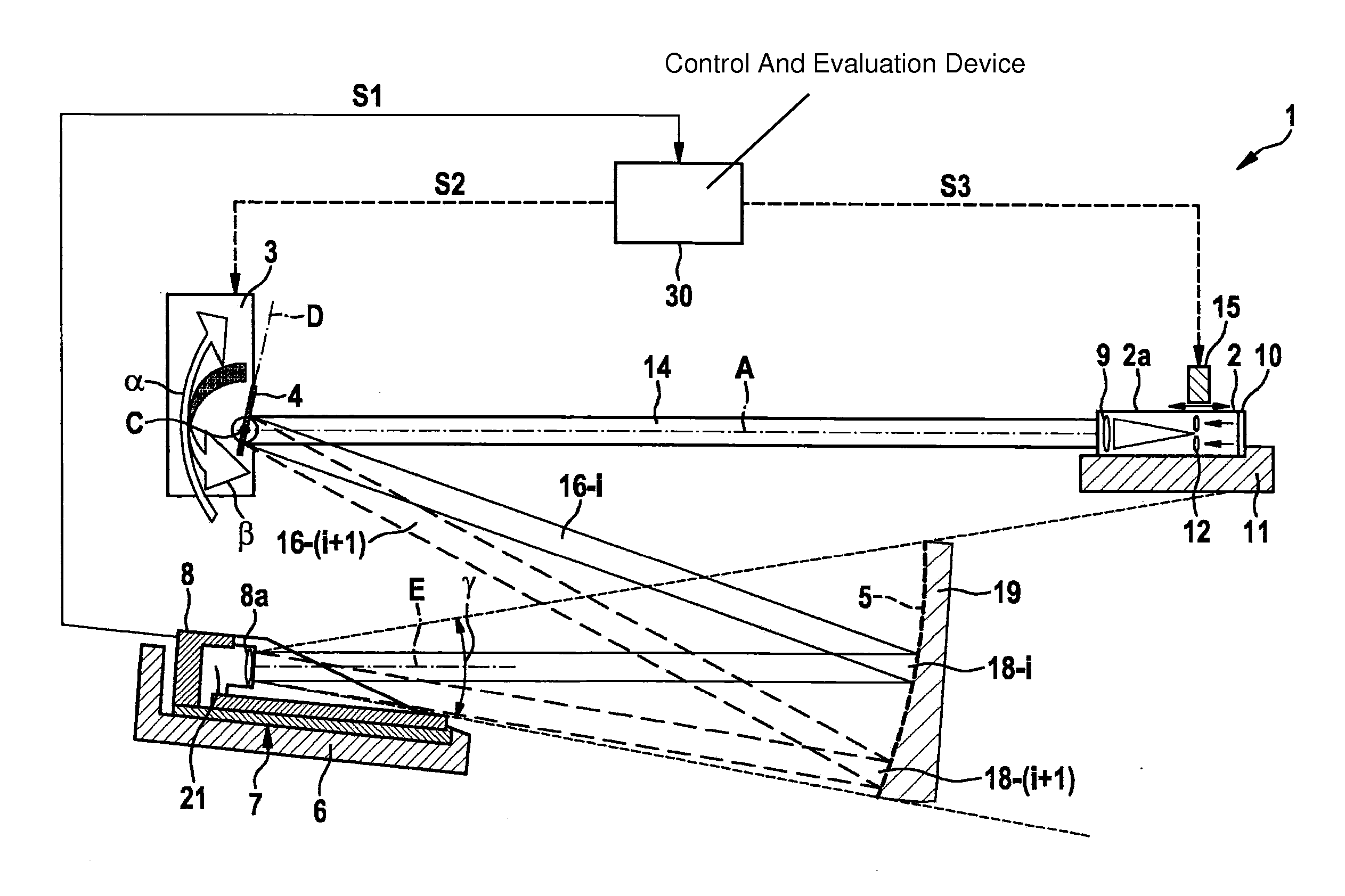
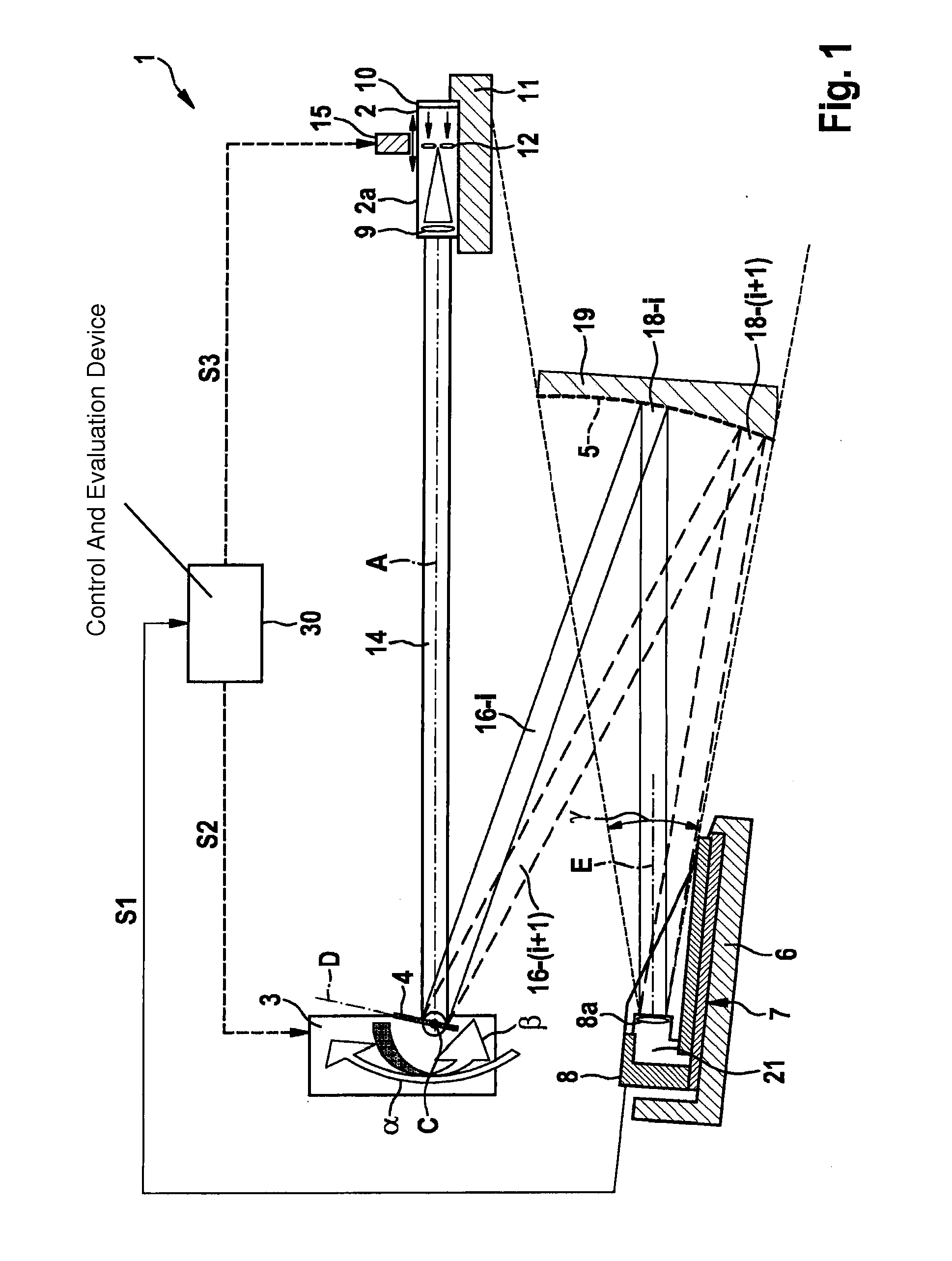
[0029]According to FIG. 1, a measuring device 1 has a focusable collimator 2 acting as a collimator device, a mirror adjustment device 3 having a pivotably accommodated first mirror 4, a fixed second mirror device 5, and a camera support 6 having a camera 8 to be tested which is accommodated in a camera position 7.

[0030]Collimator 2 has, in a manner known per se:

[0031]a housing 2a, an optics device 9, a light source, for example, in the form of an LED unit 10 in the rear area of housing 2a, and a test pattern 12 which is adjustable along optical axis A by an adjustment device 15 in housing 2a.

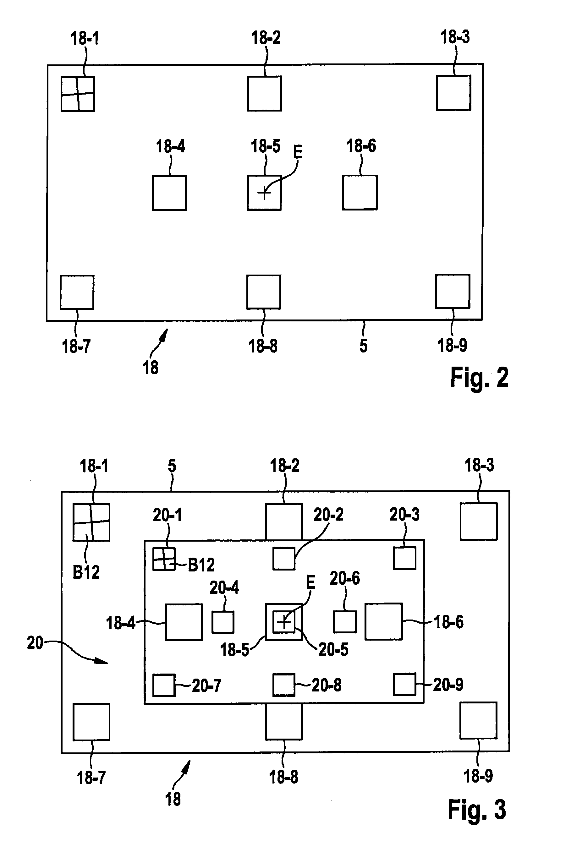
[0032]Optics device 9 is preferably an eyepiece (collective lens) having a fixed position in housing 2a. Test pattern 12 may, for example, be an etched plate or glass panel, for example, as apparent in the illustration in FIG. 3, a cross-shaped test pattern 12, which is illuminated from behind by LED unit 10 and thus appears toward the front, i.e., toward eyepiece 9, as a light-emitting object...


PUM


Abstract

A device and a method are described for measuring a camera having an image sensor, in particular a fixed-focus camera, the device including: a camera support for accommodating at least one camera to be tested in at least one camera position, a collimator device for emitting collimator light of a test pattern having different object distances, a mirror system for deflecting the collimator light to the camera position, the mirror system having at least one first mirror device which is pivotable by a mirror adjustment device into multiple pivot positions, and a second mirror device having multiple second mirror units, the second mirror units reflecting the light emitted by the first mirror device in its different pivot positions to the camera position for imaging the test pattern in different image regions of an image sensor.

Description

BACKGROUND INFORMATION[0001]Cameras which are used in driver assistance systems of vehicles are generally manufactured in a fixed-focus design, i.e., having fixed focusing. These cameras must be checked for a correct alignment of the image plane of the objective with the surface of the image sensor. For this purpose, a test pattern is generally recorded at various positions in the image field, which is projected by a motor-tunable collimator from various virtual object distances. The distance range may respectively be varied in multiple steps between infinite and 2 m in order to ascertain the object distance at which the test object is focused. An MTF (modulation transfer function) is advantageously calculated as a measure of the contrast for each position and for each object distance from the definable pulse response in the recorded image of the test pattern. The tuning of the object distance is also referred to as a through-focus scan.[0002]The cameras are generally to be focused ...

Claims


Application Information

Patent Timeline
Patent Type & Authority Applications(United States)
IPC IPC(8): G03B43/00H04N17/00G02B27/30
CPCG03B43/00H04N17/002G02B27/30G02B27/36G02B27/62
Inventor APEL, UWERAIZNER, CARINA
Owner ROBERT BOSCH GMBH
Why Eureka
Try Eureka