Imaging device, imaging method, electronic device, and program

a technology of imaging method and image data, applied in the direction of radioation control device, television system scanning details, television system, etc., can solve the problems of lowering resolution and more frequent image data folding distortion, so as to reduce resolution and reduce the sn ratio , the effect of minimizing the decrease of resolution

Active Publication Date: 2015-05-21
SONY CORP
View PDF3 Cites 13 Cited by
  • Summary
  • Abstract
  • Description
  • Claims
  • Application Information

AI Technical Summary

Benefits of technology

[0052]According to an aspect of the present technique, it is possible to restrict the lowering of the SN ratio, minimize the decrease of resolution, and perform high speed processing to improve the sensitivity of pixel signals.

Problems solved by technology

Using the addition reading, however, naturally causes lowering the resolution compared to a method of reading all the photo receiving pixels separately.
Meanwhile, folding distortion may occur more frequently in image data obtained by the thin-out reading method than in the addition reading method.

Method used


Image

  • Imaging device, imaging method, electronic device, and program
  • Imaging device, imaging method, electronic device, and program
  • Imaging device, imaging method, electronic device, and program

Examples


first embodiment

Exemplary Structure of Embodiment of Imaging Device

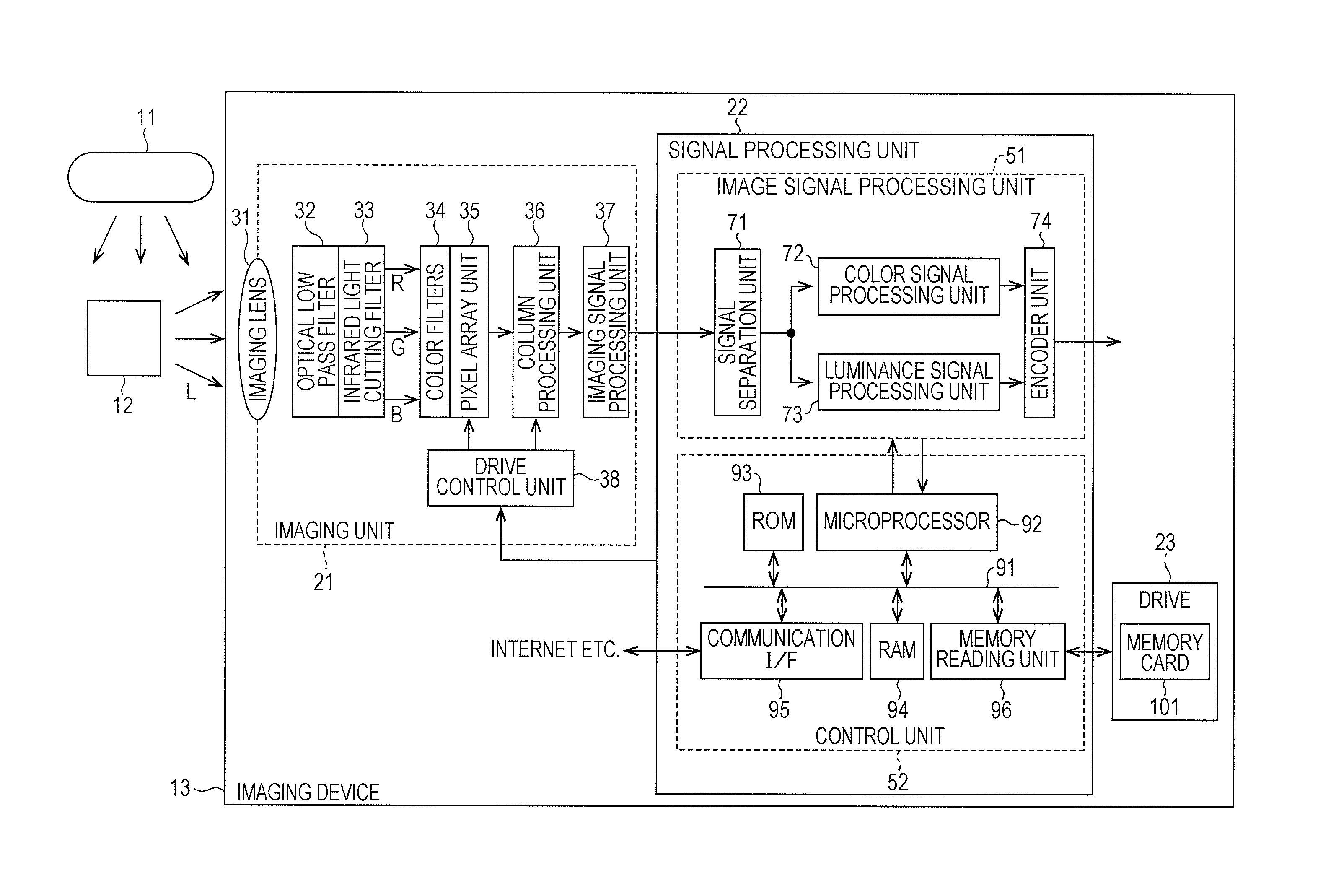
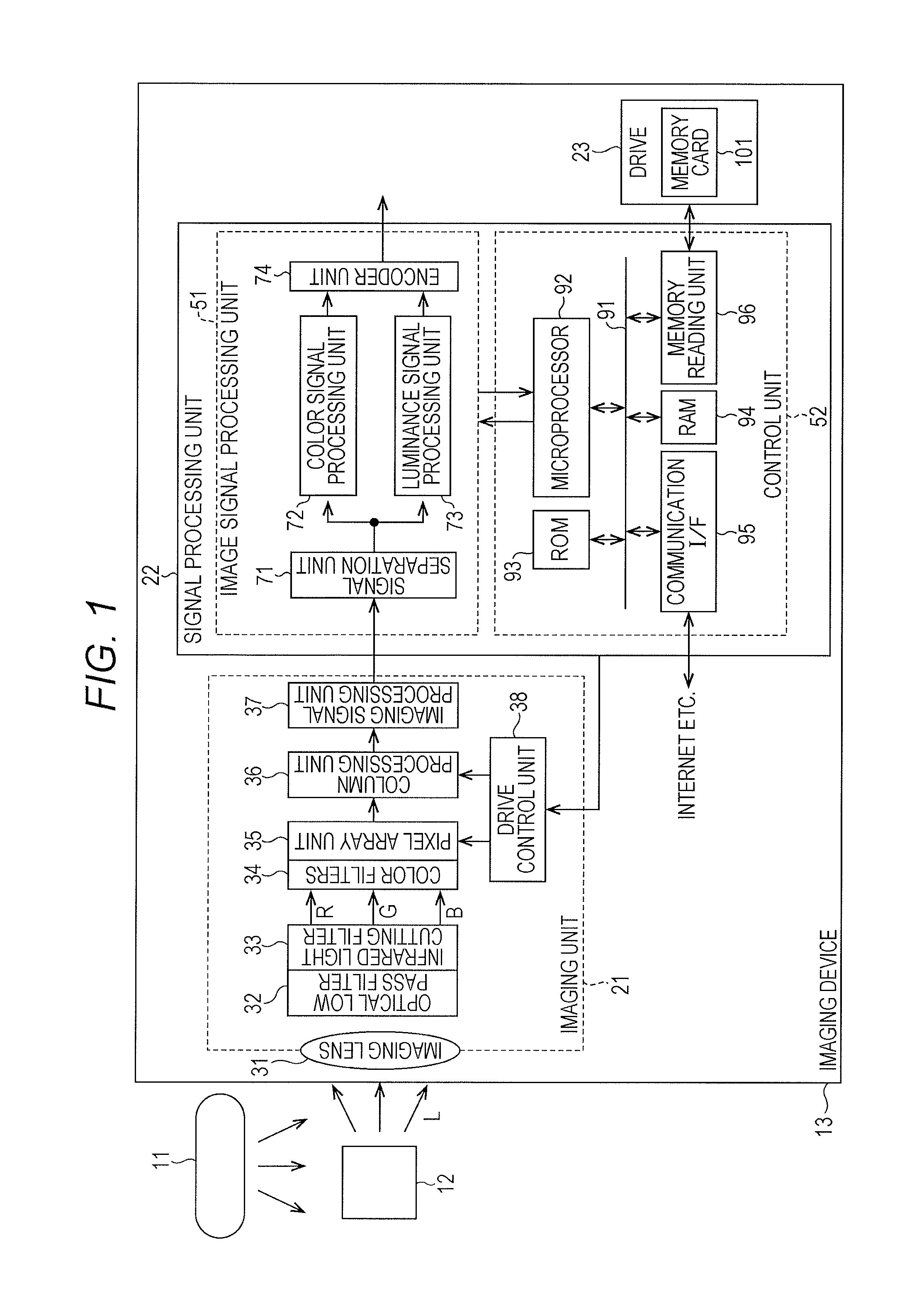
[0071]FIG. 1 is a block diagram illustrating an exemplary structure of an imaging device to which the present technique is applied according to a first embodiment. The imaging device of FIG. 1 takes an image to be output as an image signal formed by a digital signal, and records the image signal in, for example, removable media.

[0072]An imaging device 13 of FIG. 1 includes an imaging unit 21 configured to take a color image, which is formed by visible light, to be output as an image signal, and a signal processing unit 22 configured to perform signal processing of the image signal received from the imaging unit 21 and record the image signal in removable media 101, while controlling the operation of the imaging unit 21.

[0073]More specifically, the imaging unit 21 is a so-called complementary metal oxide semiconductor (CMOS) image sensor including an imaging lens 31, an optical low pass filter 32, an infrared light cutting filter 33,...


PUM


Abstract

The present technique relates to an imaging device and an imaging method, an electronic device, and a program, which are configured to improve an SN ratio by combining addition reading and thin-out reading by signal processing similar to signal processing using thin-out reading.
First, as illustrated in the left side of the drawing, G pixel and B pixel, which are sub-colors, of the top row of regions Z1, Z2 are subjected to thin-out reading. Next, for W pixels of the main color arranged in a checkerboard pattern in the regions Z1, Z2, two pixels tied by a straight line in the drawing are subjected to addition reading at the same tone timing. For W pixels of the main color arranged in a checkerboard pattern in regions Z3, Z4, two pixels tied by a straight line in the drawing are also subjected to addition reading at the same tone timing. R and G pixels, which are sub-colors, of the lower stage of the regions Z3, Z4 are read.
According to a relative relation between the main color and the sub-colors of the regions Z1 to Z4 as illustrated in the center of the drawing, Bayer arrangement is obtained as illustrated in the right side of the drawing. The present technique can be applied to an imaging device.

Description

TECHNICAL FIELD[0001]The present technique relates to an imaging device, an imaging method, an electronic device, and a program. More particularly, the present technique relates to an imaging device, an imaging method, an electronic device, and a program, which are configured to restrict reduction of a signal to noise ratio, minimize decrease of resolution, and improve sensitivity of pixel signals by high speed processing.BACKGROUND ART[0002]The present invention relates to an imaging device, such as a digital still camera and a digital video camera, and signal processing.[0003]In a solid state image sensor, such as a complementary metal oxide semiconductor (CMOS) image sensor, which attains an increased number of pixels, addition reading or thin-out reading has been used as a technique of performing high frame rate reading.[0004]Among these techniques, the addition reading method has been commonly used because of its advantage of increasing a signal to noise ratio (also referred to...

Claims


Application Information

Patent Timeline
Patent Type & Authority Applications(United States)
IPC IPC(8): H04N9/04H04N5/357H04N5/378H04N5/3745
CPCH04N9/045H04N5/37455H04N5/357H04N5/378H04N25/445H04N25/46H04N25/70H04N25/778H04N25/447H04N25/133H04N25/135H04N25/75H01L27/146H04N25/60H04N25/76H04N23/12H04N25/772
Inventor KAWAGUCHI, SHUNJIHIROTA, ISAOSHOYAMA, HIDEKI
Owner SONY CORP
Why Eureka
Try Eureka