Industrial microwave ultrasonic reactor

a technology of microwave and ultrasonic reactor, which is applied in the direction of mechanical vibration separation, energy-based chemical/physical/physical/physical-chemical processes, chemical/physical/physical-chemical processes, etc., can solve the problems of inability to achieve continuous industrial production and unsuitable for large-scale industrial production, and achieve the effect of shortening the feed and discharge time interval

Inactive Publication Date: 2015-05-28
SONGXIAN EXPLOITER MOLYBDENUM
View PDF2 Cites 19 Cited by
  • Summary
  • Abstract
  • Description
  • Claims
  • Application Information

AI Technical Summary

Benefits of technology

[0007]The technical problem to be solved by the present invention is to provide an industrial microwave ultrasonic reactor, so as to overcome problems of an existing microwave ultrasonic reactor that a treatment capacity is low, a range of action of microwave and ultrasonic wave is limited, and uniformity is poor, thereby shortening time for chemical leaching, improving the purity of an extracted product, and improving operation efficiency.
[0021]1. Operation time is shortened, and operation efficiency is improved.
[0022]By using the microwave ultrasonic reactor of the present invention, due to the unique design of the microwave generation device and the ultrasonic wave generation device, the range of action of microwave and ultrasonic wave is larger, and the uniformity is higher. In a specific implementation manner, in preparation of molybdenum disulfide by leaching out impurities from molybdenite by using the microwave ultrasonic reactor of the present invention, the operation time is shortened to be 20 to 60 min from 360 to 480 min for a conventional reactor, so that leaching time is shortened, labor intensity is lowered, and the operation efficiency is improved.
[0024]In a specific implementation manner, in preparation of molybdenum disulfide by leaching impurities from molybdenite by using the microwave ultrasonic reactor of the present invention, leaching temperature is 60° C. to 90° C., the purity of the prepared molybdenum disulfide is up to 99.9%, the leaching efficiency is significantly improved, and the purity of the purified product is improved.
[0026]The microwave ultrasonic reactor of the present invention overcomes the disadvantage that the prior art most is confined in treatment of a small quantity of samples in the laboratory, can be adaptively designed according to the wave absorption properties of solid and liquid materials and industrial demands, a reactor capacity can be designed to be 2 m3 and more, thereby actually implementing industrialization. Moreover, the microwave units and the ultrasonic pulse units have independent power switches based on the set, when a treatment capacity is reduced, corresponding sets can be suitably turned off, thereby flexibly matching changes in production and saving energy.
[0028]According to the microwave ultrasonic reactor of the present invention, because microwave is used for rapid heating and ultrasonic vibration is used to strengthen a heterogeneous reaction process, and the circulation pipe is disposed to intensify stirring and mixing, the chemical processes such as leaching and dissolution are significantly accelerated, and the feed and discharging time interval is shortened, thereby implementing continuous production.

Problems solved by technology

However, the reactor is a small laboratory apparatus, and the sample treatment capacity of the reaction system is low; therefore, once the reactor is used in an industrial process, addition of a large amount of raw materials, freely moving and lifting the apparatus, uniformly mixing of heterogeneous reaction materials, and the range of action and the uniformity of microwave and ultrasonic wave cannot be solved by multiple amplification of the capacity of the reaction vessel, that is, these techniques are not suitable for large-scale industrial production, and cannot achieve continuous industrial production.

Method used


Image

  • Industrial microwave ultrasonic reactor
  • Industrial microwave ultrasonic reactor
  • Industrial microwave ultrasonic reactor

Examples


embodiment 1

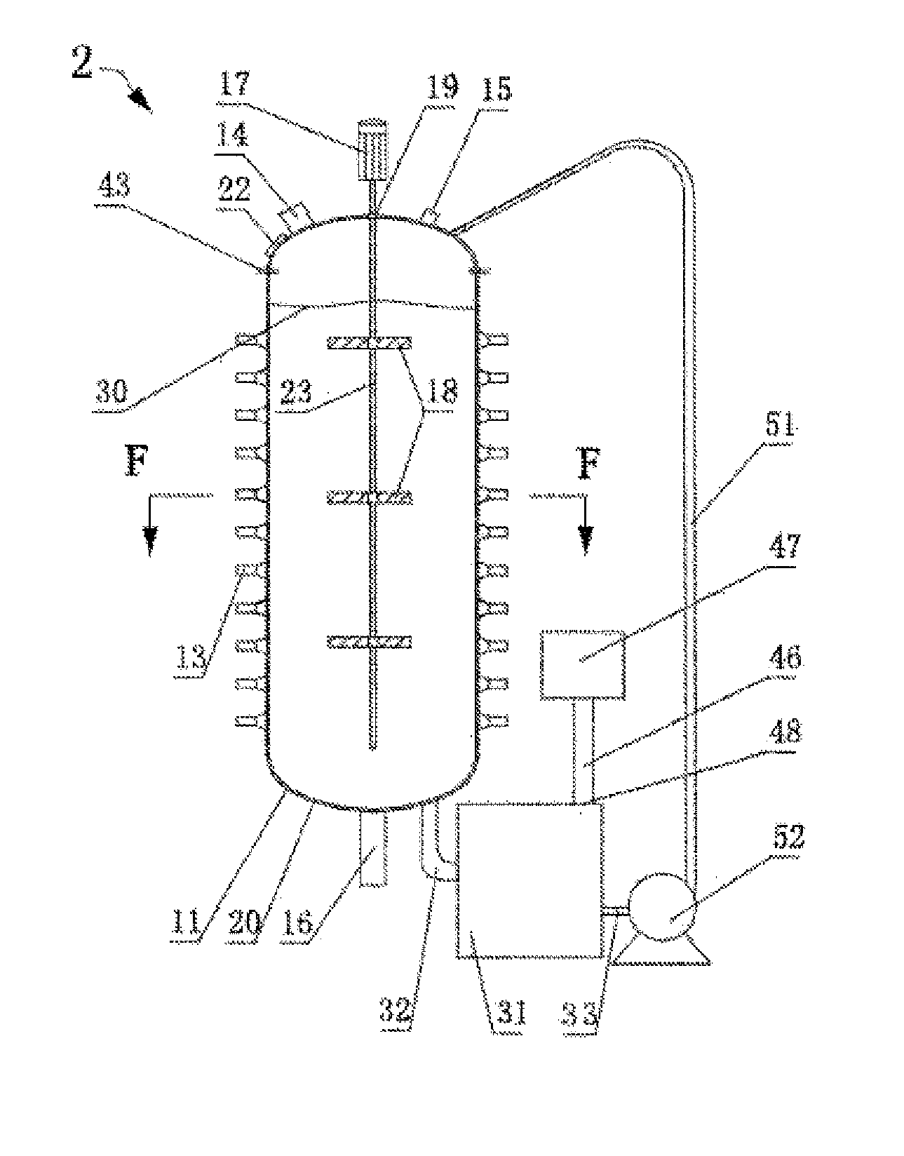
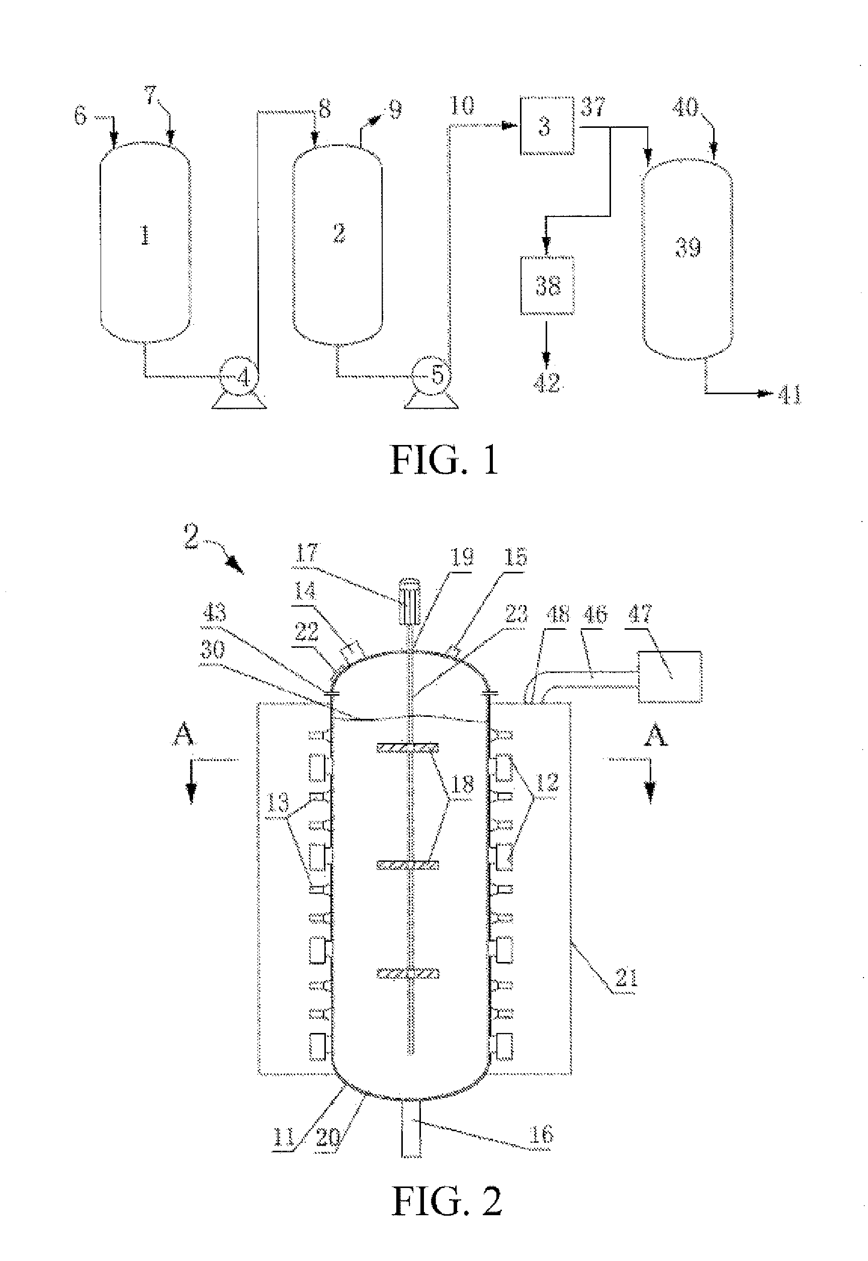
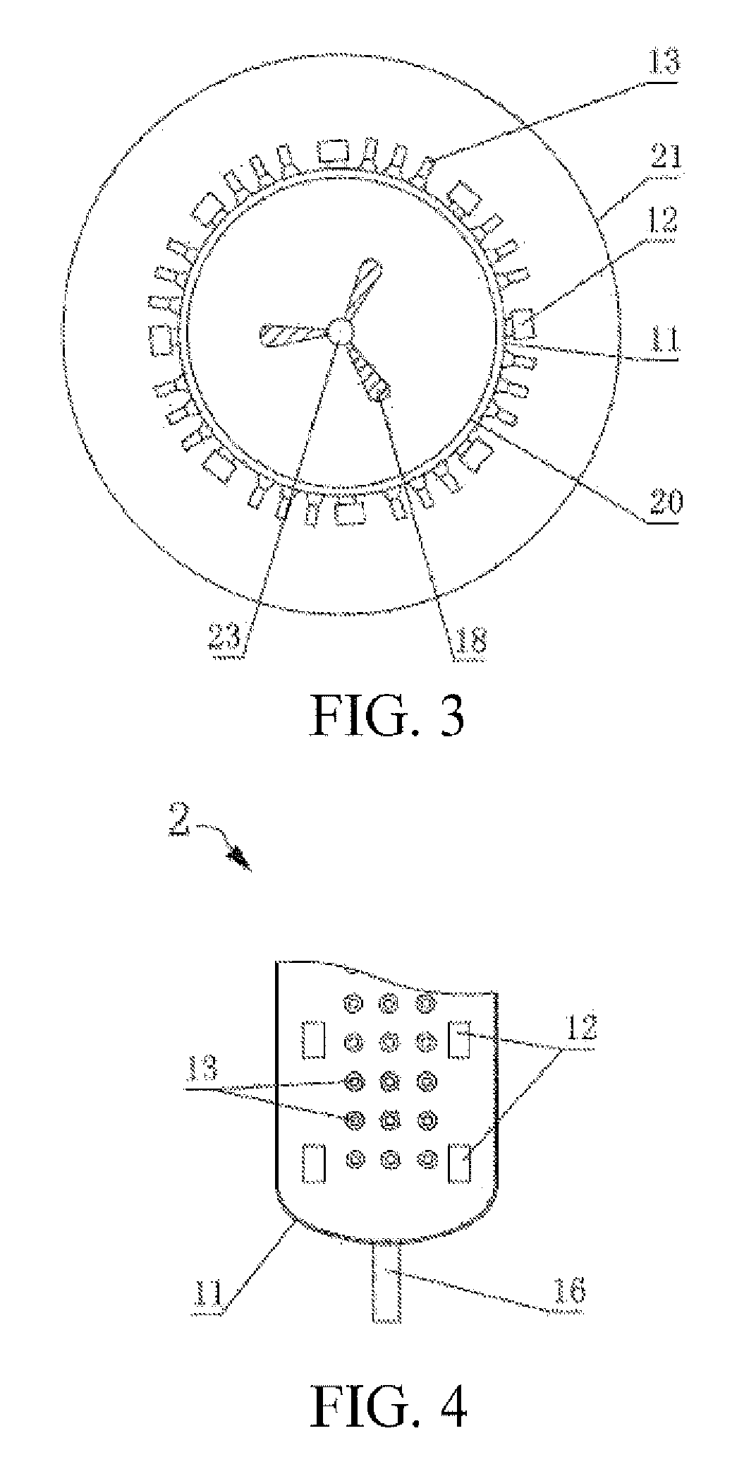
[0059]As shown in FIG. 2, FIG. 3, FIG. 4, and FIG. 5, a microwave ultrasonic wave reactor 2 includes a reactor 11, a microwave generation device, an ultrasonic wave generation device, a stirring device, and a heat removal device. A feed port 14, an exhaust port 15, a view window 22, a pressure relief valve, and a pressure gauge (not shown in the figures) are disposed at the top of the reactor 11, and a discharge port 16 is disposed at the bottom of the reactor 11.

[0060]The reactor 11 is a cylindrical reactor, and a liner of the reactor 11 is made of an anti-corrosion wave-transmitting material, and preferably is a PTFE coating 20 having a thickness being 0.05 to 1 mm, so as to prevent apparatus corrosion due to direct contact of the reactor with the leaching solution such as hydrochloric acid, hydrofluoric acid, and a chloride salt.

[0061]The microwave generation device includes 4 sets of microwave units 12 that are horizontally arranged, and each set has 8 microwave units 12 arrange...

embodiment 2

[0066]As shown in FIG. 6, FIG. 7, FIG. 8, and FIG. 9, a microwave ultrasonic wave reactor 2 of the present invention includes a reactor 11, a microwave generation device, an ultrasonic wave generation device, a stirring device, a heat removal device, and a circulation pipe 26. A feed port 14, an exhaust port 15, and a view window 22 are disposed at the top of the reactor, and a discharge port 16 is disposed at the bottom of the reactor 11.

[0067]The reactor 11 is a cylindrical reactor, as shown in FIG. 9. A liner of the reactor is a release anti-corrosion barrel 24 having a shape matching a shape of an inner wall of the reactor 11, a reduced diameter, and a thickness being 3 to 30 mm, such as a PP barrel. Wave-transmitting glass wool 25 is disposed between the release anti-corrosion barrel 24 and the reactor 11, so that the release anti-corrosion barrel 24, the glass wool 25, and the reactor 11 are closely adhered to each other from inside to outside.

[0068]The microwave generation de...

embodiment 3

[0073]As shown in FIG. 10, FIG. 11, FIG. 12, and FIG. 13, a microwave ultrasonic wave reactor 2 of the present invention includes a reactor 11, a microwave generation device, an ultrasonic wave generation device, a stirring device, a heat removal device, a guard disc 29, and a return pipe I 34. A feed port 14, an exhaust port 15, and a view window 22 are disposed at the top of the reactor, and a discharge port 16 is disposed at the bottom of the reactor 11.

[0074]As shown in FIG. 11, the reactor 11 is a cylindrical reactor, and a liner of the reactor 11 is a PTFE coating 20 closely adhered to an inner wall of the reactor 11 and having a thickness being 0.05 to 3 mm.

[0075]The microwave generation device includes 4 sets of microwave units 12 that are horizontally arranged, each set has 8 microwave units 12 arranged at intervals along the circumferential direction of the outer sidewall of the reactor 11. The microwave unit 12 includes a magnetron, a diode, a transformer, and a waveguide...


PUM

PropertyMeasurementUnit
thicknessaaaaaaaaaa
thicknessaaaaaaaaaa
magnetron poweraaaaaaaaaa

Abstract

An industrial microwave ultrasonic reactor has an inner wall liner. A microwave generation device is formed by microwave units distributed on an outer sidewall, or by a microwave pipe disposed outside the reactor and microwave units distributed on the microwave pipe. One end of the microwave pipe communicates with the bottom of the reactor via a connection pipe I, and the other end communicates with the top via a return pipe. A shield is disposed outside the microwave generation device to separate the microwave units from the outside, and a heat removal device is disposed outside the shield. An ultrasonic wave generation device is formed by 10 to 30 sets of ultrasonic pulse units disposed at intervals along the outer sidewall. Each set has 10 to 50 members distributed along the circumferential direction of the reactor. A stirring shaft is fixed below a stirring motor and extends into the reactor.

Description

BACKGROUND[0001]1. Field of the Invention[0002]The present invention relates generally, to the field of physical / chemical reaction engineering equipment and relates more specifically to an industrial microwave ultrasonic reactor.[0003]2. Related Art[0004]Microwave is a type of electromagnetic wave having a wavelength in the range of those of infrared ray and ultrasonic wave, and has a wavelength in the range of 1 m to 1 mm and a frequency being 300 MHz to 300 KMHz. Microwave heating is to induce molecular polarization and dipole rotation by means of interaction between microwave and molecules, so as to cause rapid movement of molecules. Therefore, microwave heating has strong penetration effect and can reach the internal of materials, so that the temperature inside the materials is rapidly increased, and ingredients are freely released, thereby achieving the purpose of removing or extracting the ingredients, and meanwhile, the reaction rate is significantly increased, and the chemic...

Claims


Application Information

Patent Timeline
Patent Type & Authority Applications(United States)
IPC IPC(8): B01J19/10B01J19/18B01J19/02B01J19/12B01J19/00
CPCB01J19/10B01J19/126B01J19/0066B01J19/02B01J2219/1272B01J2219/0209B01J2219/1242B01J2219/1215B01J19/18B01J19/1881B01J19/2415B01J19/243B01J2219/0245B01J2219/1284B01J2219/1296C22B4/00C22B34/34
Inventor ZHAO, WEIGENZHAO, LONGFEILI, NIANFAN, JIAFU
Owner SONGXIAN EXPLOITER MOLYBDENUM
Why Eureka
Try Eureka