
Coil unit

a coil and coil technology, applied in the direction of transformer/inductance magnetic cores, transformer/inductance cores, cores/yokes, etc., can solve the problems of low power transmission efficiency, unfavorable magnetic field formation, and significant decease, so as to reduce unwanted leakage magnetic field, reduce the magnetic coupling between coils, and facilitate circulation

Active Publication Date: 2015-05-28
TDK CORPARATION
View PDF5 Cites 12 Cited by
  • Summary
  • Abstract
  • Description
  • Claims
  • Application Information

AI Technical Summary

Benefits of technology

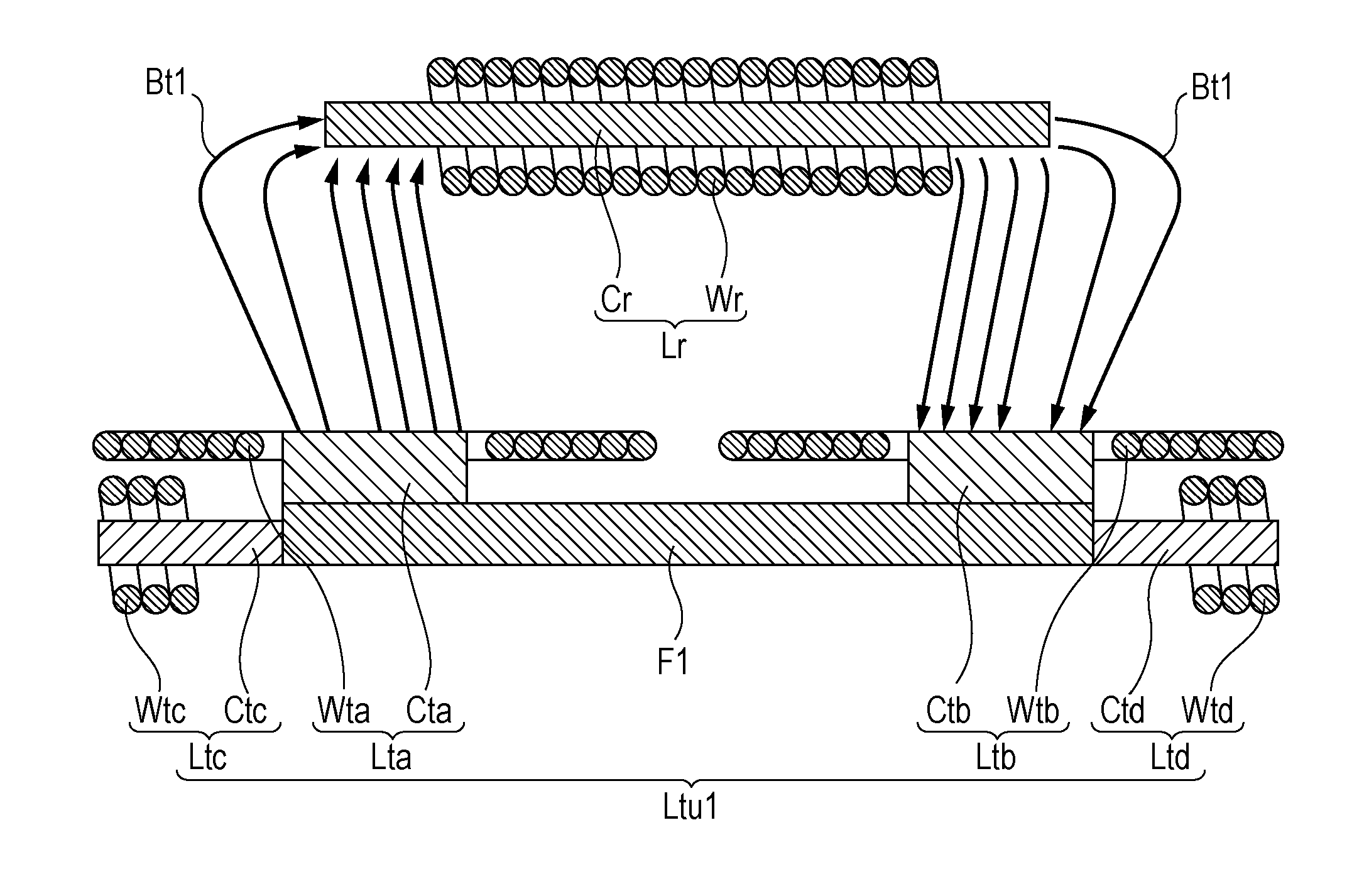
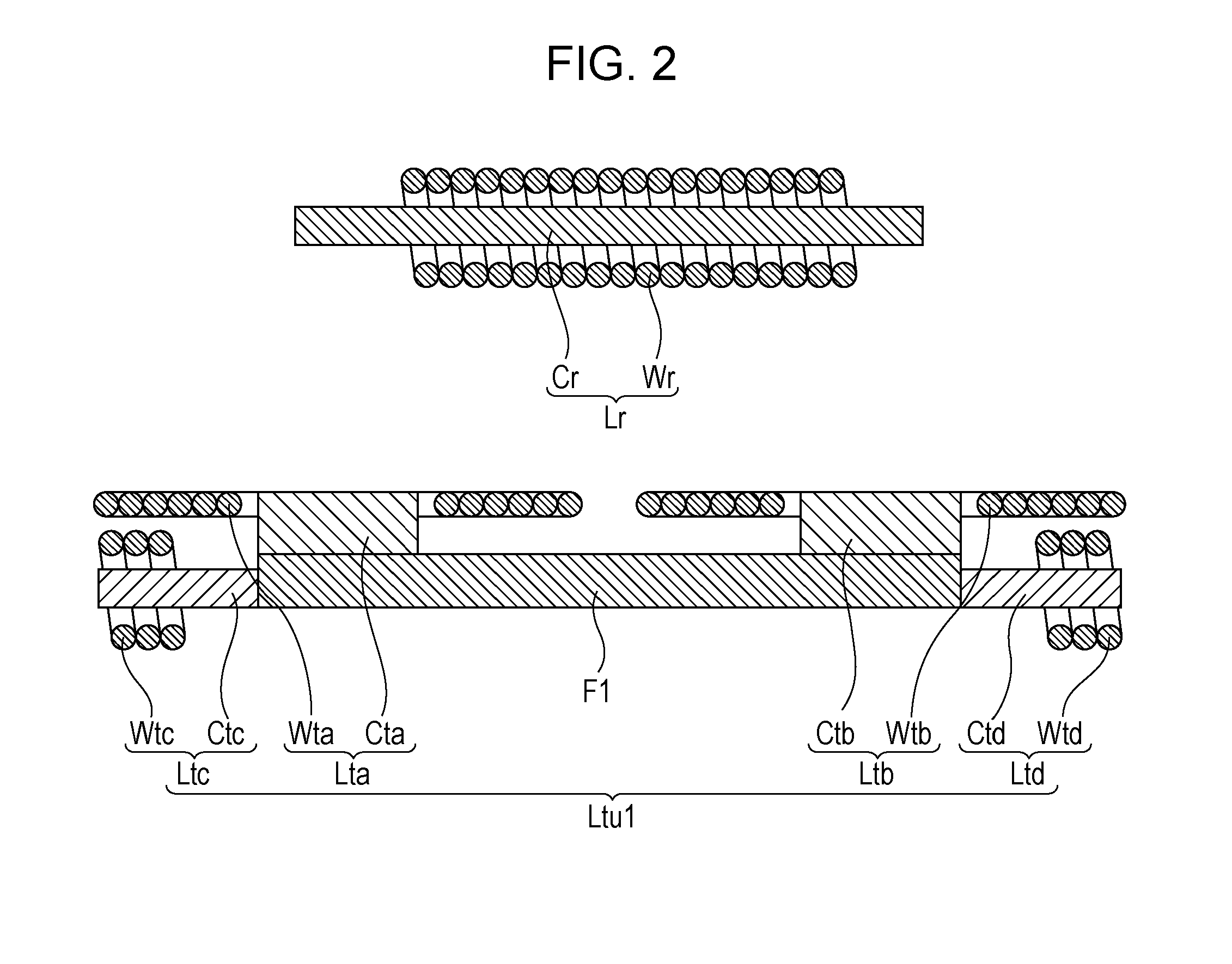
The present invention provides a coil unit that reduces an unwanted leakage magnetic field while maintaining a strong magnetic coupling between coils even if there is a displacement between them. The coil unit includes four coils that are interlinked with each other, and the directions of the currents flowing in the coils are matched each other. The coils are arranged in a way that allows a magnetic flux that contributes to power transmission to easily circulate also in a location away from the coil unit, and a magnetic flux that cancels out the leakage magnetic field is also circulated in the same location. This results in a reduction in the unwanted leakage magnetic field and prevents a reduction in the magnetic coupling between coils. The coil unit is controlled by a drive control unit that matches the directions or phases of the current flowing in each of the coils. The configuration of the coils allows for efficient generation of magnetic flux that contributes to power transmission and cancels out the leakage magnetic field. The coil unit is designed to minimize the unwanted leakage magnetic field and prevent it from affecting other components or devices.

Problems solved by technology

Such a displacement between the power feeding coil and the power receiving coil would cause a significant decease in magnetic coupling between the coils, which may entail the problem of low power transmission efficiency.
On the contrary, it is problematic that the unwanted leakage magnetic field is likely to be formed in a location away from the coils.
In particular, in the application of wireless power transmission technology to a charger for a power electronic device such as an electric vehicle, a large current needs to flow through a coil in order to meet the demand for high-power transmission, causing an increase in the strength of a leakage magnetic field formed in a location away from the coils.
This may cause electromagnetic interference which might affect nearby electronic equipment and so forth.

Method used


Image

  • Coil unit
  • Coil unit
  • Coil unit

Examples


Embodiment Construction

[0023]An embodiment of the present invention will be described in detail with reference to the drawings. In the following description, substantially the same elements or elements having substantially the same function are given the same numerals or signs, and are not described again.

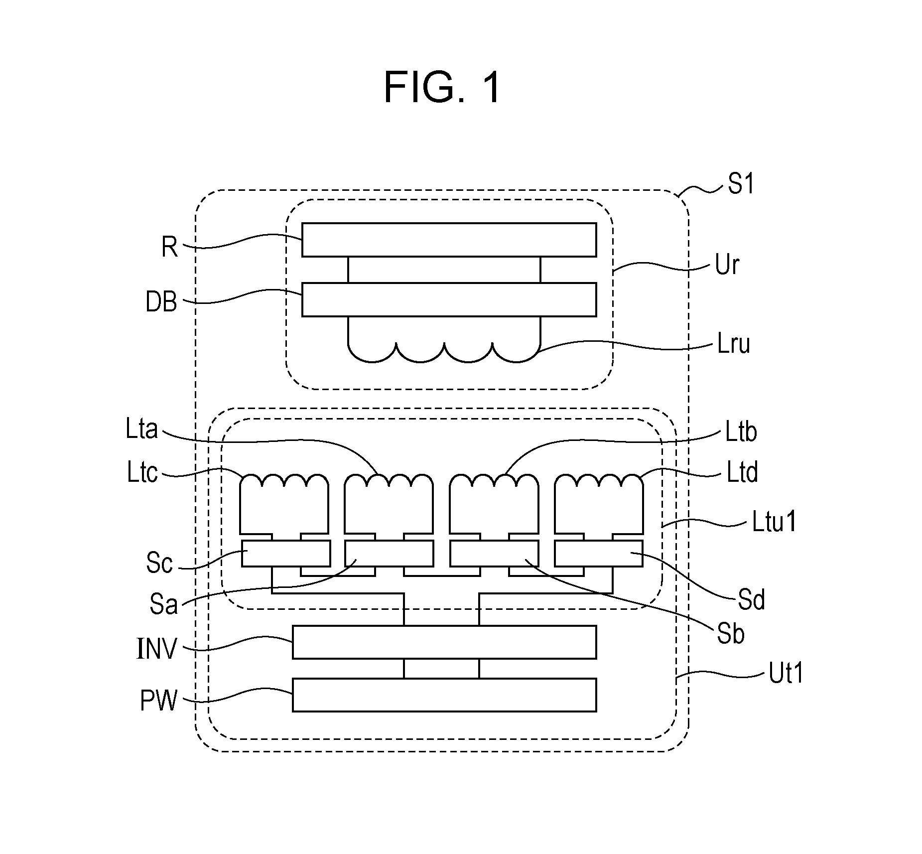
[0024]First, an overall configuration of a wireless power transmission device S1 to which a coil unit according to a preferred embodiment of the present invention is applied will be described with reference to FIG. 1. FIG. 1 is a system configuration diagram illustrating a wireless power transmission device to which the coil unit according to the preferred embodiment of the present invention is applied, together with a load. The coil unit according to the preferred embodiment of the present invention is applicable to either a power feeding coil unit in a wireless power feeding device or a power receiving coil unit in a wireless power receiving device. In the following embodiment, an example in which the ...


PUM

PropertyMeasurementUnit
diameteraaaaaaaaaa
diameteraaaaaaaaaa
thicknessaaaaaaaaaa

Abstract

A coil unit includes first and second coils that are apposed, and third and fourth coils located on the rear side of the first and second coils so as to interpose the center of the first coil and the center of the second coil between the third and fourth coils, in the direction of alignment of the first and second coils. The axial direction of the third and fourth coils is substantially perpendicular to the axial direction of the first and second coils. First to fourth drive control units control the directions or phases of the currents to be supplied to the first to fourth coils, respectively.

Description

BACKGROUND OF THE INVENTION[0001]1. Field of the Invention[0002]The present invention relates to a coil unit for wirelessly feeding or receiving power.[0003]2. Description of the Related Art[0004]Wireless power transmission technology that utilizes an electromagnetic induction effect between a primary (power feeding) coil and a secondary (power receiving) coil that face each other to transmit power without any mechanical contact such as a cable has attracted attention recently.[0005]In the application of the wireless power transmission technology described above to devices for power supply of electric vehicles and the like, it is anticipated that the positional relationship between a power feeding coil installed in the ground or the like and a power receiving coil mounted in an electric vehicle or the like will not necessarily be constant. Such a displacement between the power feeding coil and the power receiving coil would cause a significant decease in magnetic coupling between th...

Claims


Application Information

Patent Timeline
Patent Type & Authority Applications(United States)
IPC IPC(8): H01F27/34H01F27/24H01F27/28H02J5/00
CPCH01F27/346H01F27/2804H01F27/24H02J5/005H01F3/10H01F27/38H01F38/14H04B5/00H02J50/10H02J50/70
Inventor CHIYO, NORITAKA
Owner TDK CORPARATION
Learn More