Coated x-ray window

a technology of x-ray window and coating, which is applied in the direction of x-ray tube, x-ray tube structure circuit elements, x-ray tube vessels/containers, etc., can solve the problem of hammering the self-cleaning action of the window, and achieve the effect of improving the robustness of self-heating function and improving the robustness against contamination

a technology of x-ray window and coating, which is applied in the direction of x-ray tube, x-ray tube structure circuit elements, x-ray tube vessels/containers, etc., can solve the problem of hammering the self-cleaning action of the window, and achieve the effect of improving the robustness of self-heating function and improving the robustness against contamination

US20150146866A1Active Publication Date: 2015-05-28EXCILLUM

Image

  • Coated x-ray window
  • Coated x-ray window
  • Coated x-ray window

Examples


embodiment 1

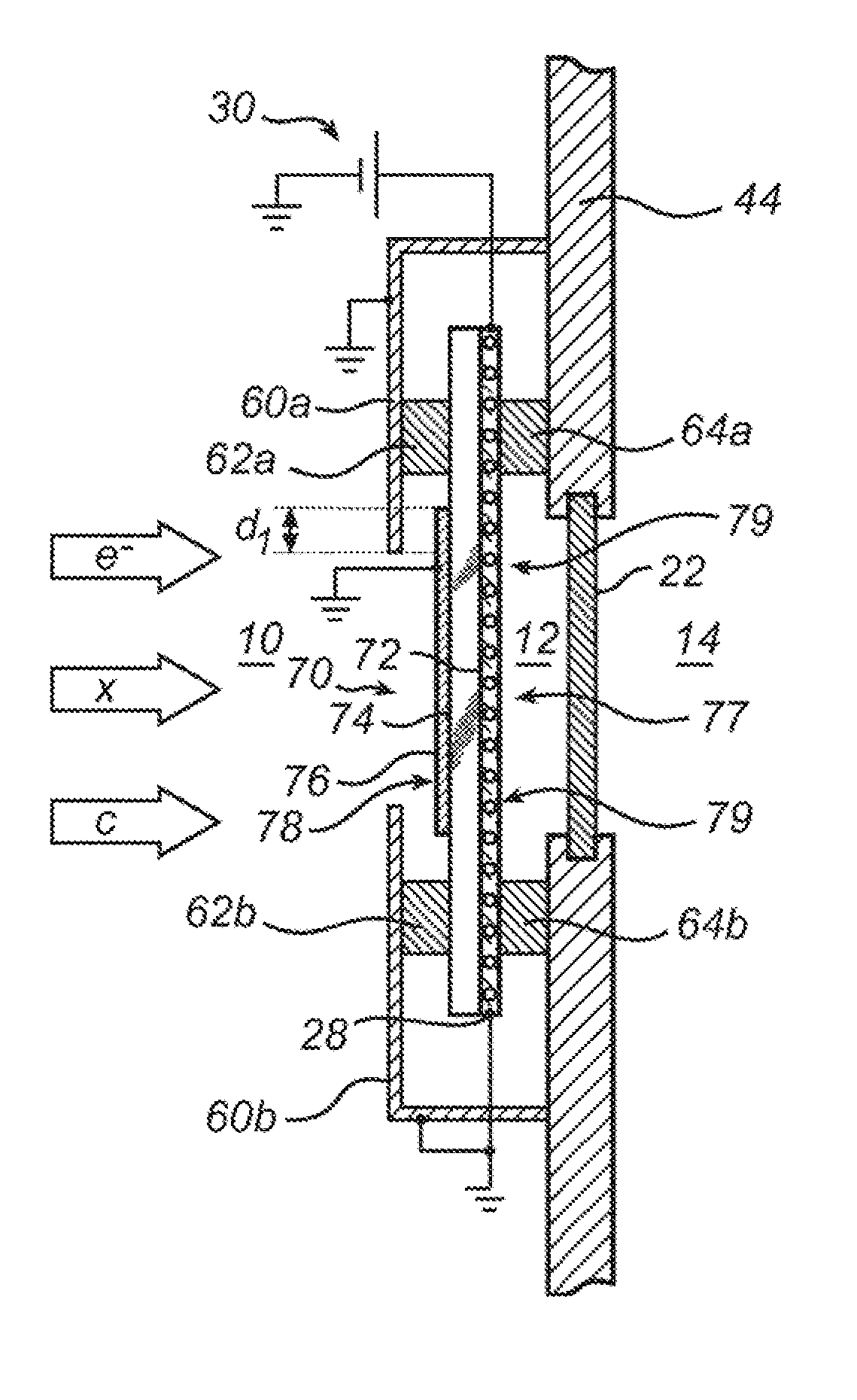
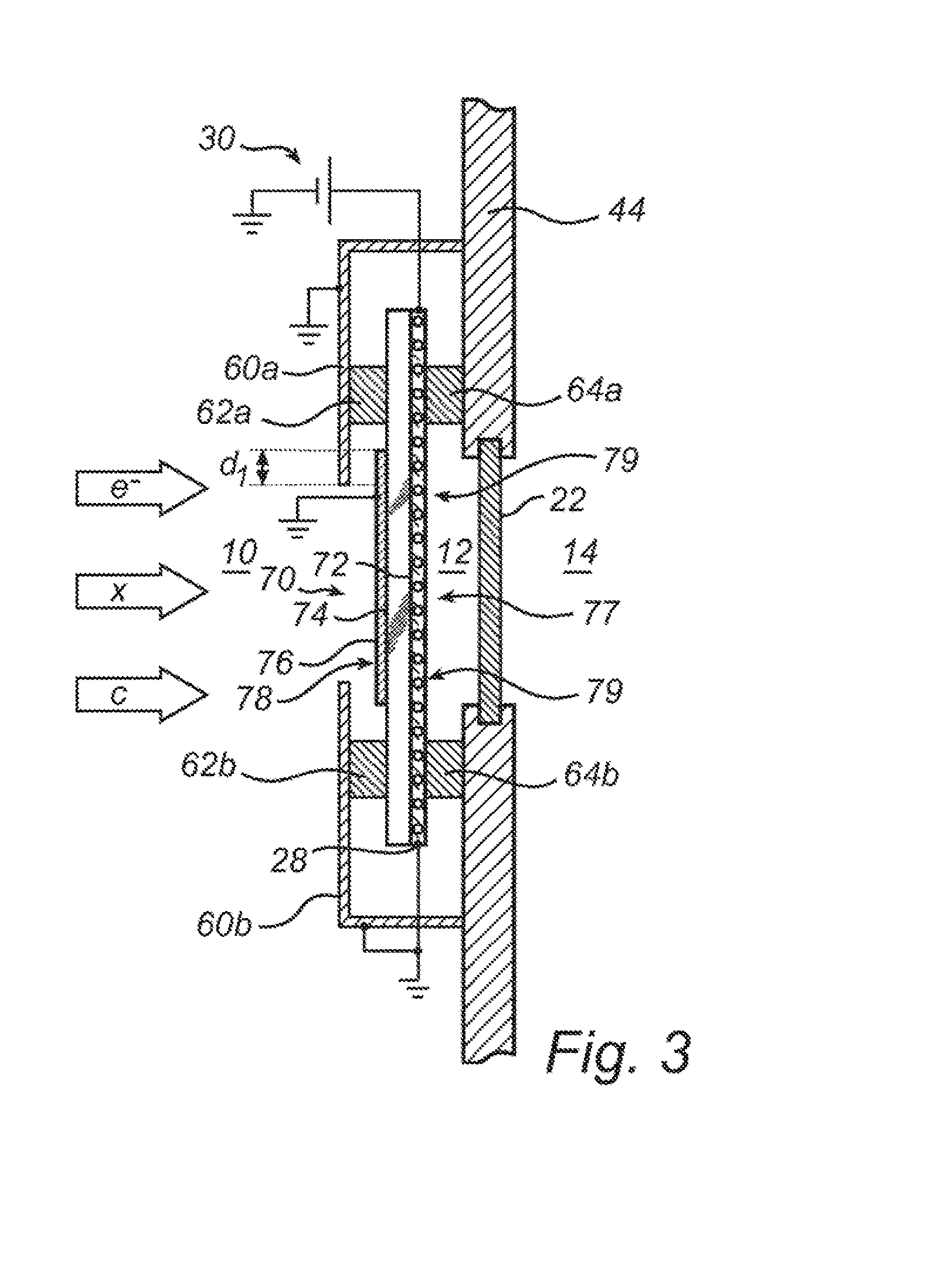
[0083]2. The X-ray window of embodiment 1, further comprising a screen (60), at least partially surrounding said secondary window element (70) on the side (78) facing the reduced pressure region, said screen being electrically conducting and connected to a charge sink.

embodiment 2

[0084]3. The X-ray window of embodiment 2, wherein the charge-drain layer (76) is completely surrounded by the screen and overlaps by a distance (d1) with the screen.

[0085]4. The X-ray window of embodiment 2 or 3, wherein the screen and said secondary window element are thermally insulated from one another.

embodiment 4

[0086]5. The X-ray window of embodiment 4, further comprising a thermally insulating spacer (66) arranged between the screen and the charge-drain layer of the secondary window element and being in electric contact with both.


PUM


Abstract

An X-ray window includes a primary and a secondary window element. In order to evaporate debris by ohmic heating, current flows through the secondary (upstream) window element. Meanwhile, electric charge originating from electron irradiation and / or depositing charged particles is to be drained off the secondary window element via a charge-drain layer. To prevent large debris particles from short-circuiting the secondary window element, the current for heating the window element flows through heating circuitry which is electrically insulated from the charge-drain layer.

Description

TECHNICAL FIELD OF THE INVENTION[0001]The invention disclosed herein generally relates to the installation of electron-impact X-ray sources. More particularly, it relates to an X-ray window suitable as a part of a vacuum casing for an X-ray generation arrangement including a liquid-jet anode.BACKGROUND OF THE INVENTION[0002]The co-pending International Application published as WO 2010 / 083854, which is incorporated herein by reference, discloses a self-cleaning window arrangement for separating atmospheric pressure from vacuum while letting X-ray radiation pass through. The window arrangement has heating means for cleaning an inner surface, facing the vacuum, in order to evaporate a contaminant during operation. In particular, the window can be cleaned from splashes, droplets and depositing mist from the liquid-jet anode.SUMMARY OF THE INVENTION[0003]It is an object of the present invention to propose an X-ray window with an improved robustness against contamination. A particular obj...

Claims


Application Information

Patent Timeline
28 May 2015
Publication
US20150146866A1
IPC
H01J35/18; H05G1/02
CPC
H05G1/02; H01J35/18; H01J35/025
Inventors
TUOHIMAA, TOMI; HEMBERG, OSCAR