Turn broach machine

a broach machine and turning technology, applied in broach machines, milling cutters, manufacturing tools, etc., can solve the problems of increased work time and achieve the effect of enhancing coupling for

Active Publication Date: 2015-05-28
HYUNDAI MOTOR CO LTD
View PDF2 Cites 2 Cited by
  • Summary
  • Abstract
  • Description
  • Claims
  • Application Information

AI Technical Summary

Benefits of technology

[0010]Various aspects of the present invention provide for a turn broach machine capable of enhanc...

Problems solved by technology

In addition, after the segment interval is adjusted, reassembling should be performed, which is inconvenient.
Further, in the case in w...

Method used


Image

  • Turn broach machine
  • Turn broach machine
  • Turn broach machine

Examples


Embodiment Construction

[0033]Reference will now be made in detail to various embodiments of the present invention(s), examples of which are illustrated in the accompanying drawings and described below. While the invention(s) will be described in conjunction with exemplary embodiments, it will be understood that present description is not intended to limit the invention(s) to those exemplary embodiments. On the contrary, the invention(s) is / are intended to cover not only the exemplary embodiments, but also various alternatives, modifications, equivalents and other embodiments, which may be included within the spirit and scope of the invention as defined by the appended claims.

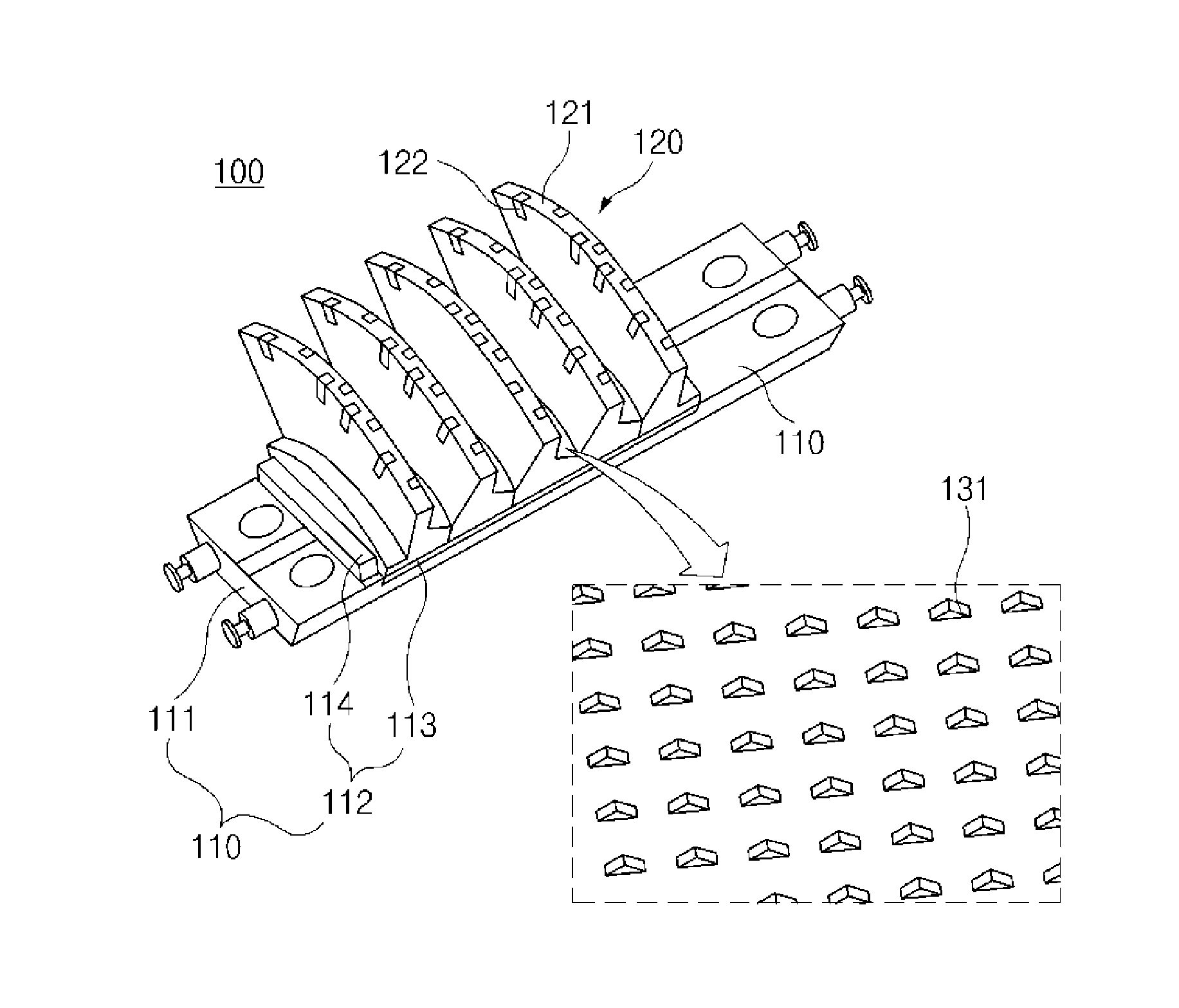
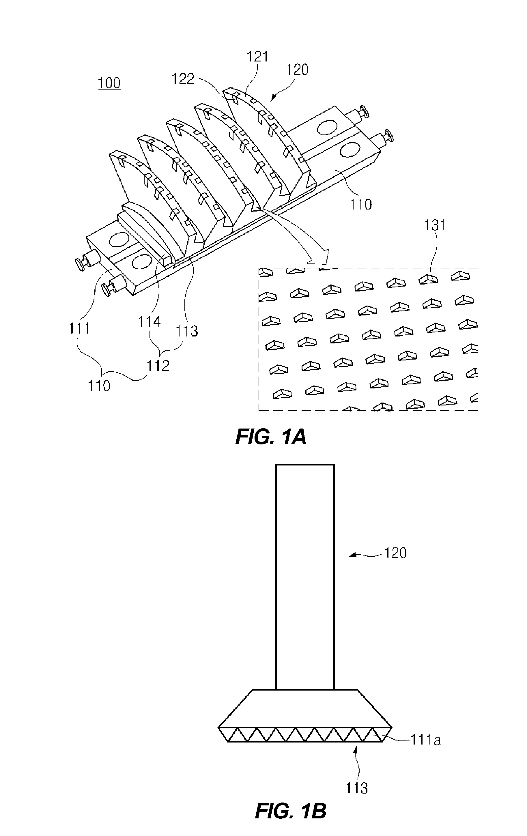
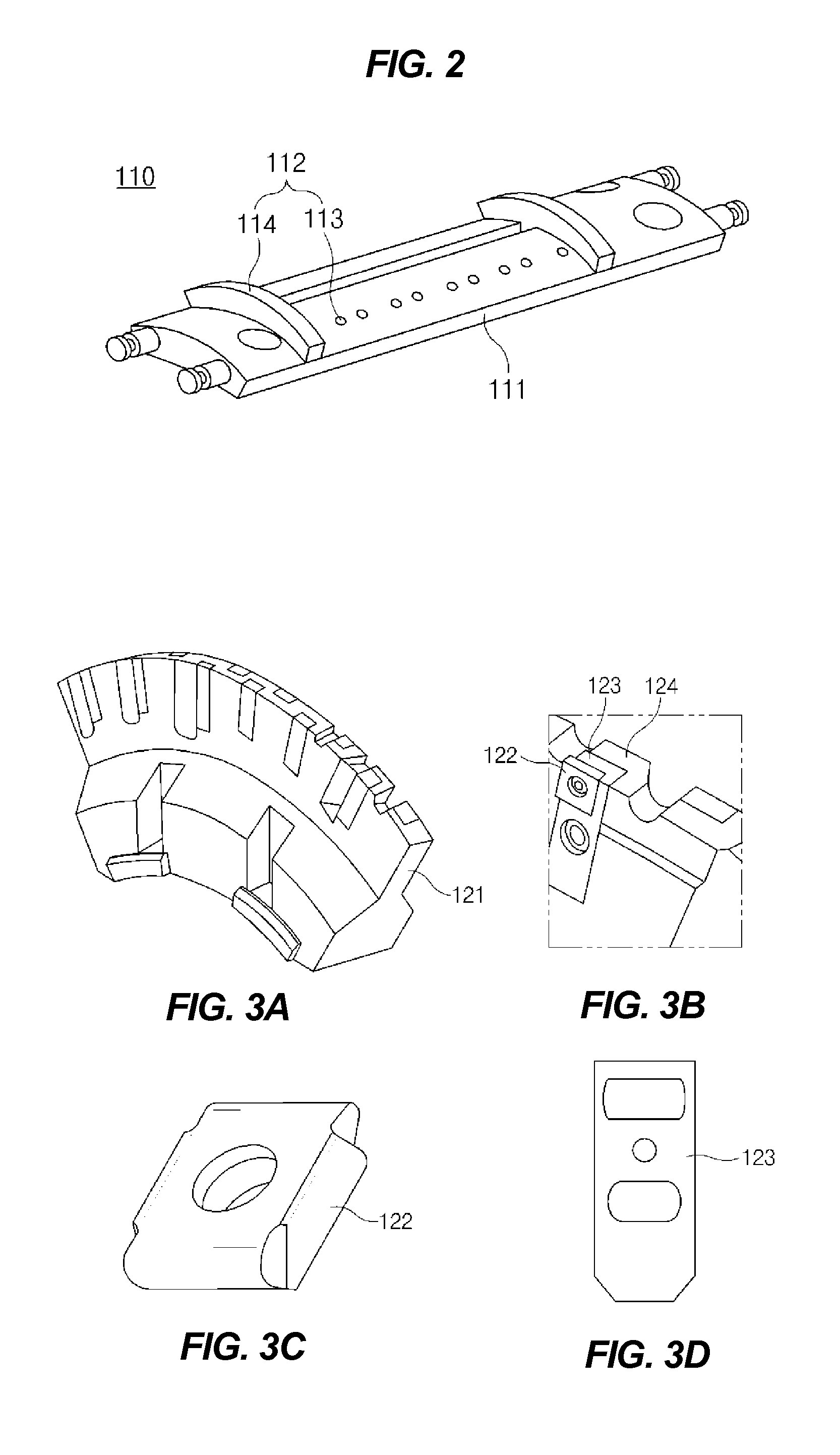
[0034]A turn broach machine according to various embodiments of the present invention is configured to include a machining member 120 machining a target to be cut (e.g., cutting material from a workpiece) and an adaptor 110 provided under the machining member 120 and supporting the machining member 120 while adjusting a position of th...


PUM

PropertyMeasurementUnit
Shapeaaaaaaaaaa

Abstract

A turn broach machine includes: a machining member machining a target to be cut; and an adaptor provided under the machining member, supporting the machining member, and adjusting a position of the machining member. At the time of adjusting a position of a segment of the machining member from a plate provided in an adapter, the segment does not manually move, but moves on an adjusting plate that is mechanically defined, such that work accuracy may be improved to increase marketability and a work time may be decreased to improve work convenience and productivity.

Description

CROSS-REFERENCE TO RELATED APPLICATION[0001]The present application claims priority of Korean Patent Application Number 10-2013-0144722 filed Nov. 26, 2013, the entire contents of which application is incorporated herein for all purposes by this reference.BACKGROUND OF INVENTION[0002]1. Field of Invention[0003]The present invention relates to a turn broach machine, and more particularly, to a turn broach machine capable of enhancing coupling force between a plate and segments and adjusting positions of the segments from the plate.[0004]2. Description of Related Art[0005]Generally, a crank for an engine is a single product manufactured by components such as a crack throw, a pin, and an end journal. Therefore, the crank for an engine should be machined in consideration of all of deformation due to heat, the radially assembled crank throw, deformation of a shape of the crack throw, and the like.[0006]In order to correct run out and deflection values of the crank, a journal machining de...

Claims


Application Information

Patent Timeline
IPC IPC(8): B23D41/04
CPCB23D41/04B23D43/06B23C2210/244B23D2043/063Y10T407/1628B23C5/08B23C5/24B23C5/2234
Inventor KIM, TAE JIN
Owner HYUNDAI MOTOR CO LTD
Why Eureka
Try Eureka