
Vacuum scavenging in hybrid vehicles

a hybrid vehicle and vacuum scavenging technology, applied in the direction of braking systems, process and machine control, instruments, etc., can solve the problems of depleting the vacuum of the brake booster, affecting the fuel economy, and affecting the operation of the brake booster

Active Publication Date: 2015-06-11
FORD GLOBAL TECH LLC
View PDF22 Cites 12 Cited by
  • Summary
  • Abstract
  • Description
  • Claims
  • Application Information

AI Technical Summary

Benefits of technology

The invention relates to a system for improving the performance and fuel economy of vehicle engines. It does this by using aspirators to generate vacuum, which is then used to power various devices such as brake boosters. By supplying vacuum to the brake booster even when it is already at a high level, the system reduces the frequency of engine pull-ups, resulting in improved fuel economy.

Problems solved by technology

Namely, closing the throttle when supplying vacuum to vacuum actuated devices when a vacuum level of a vacuum actuated device is below a threshold level may be detrimental to fuel economy, engine emissions, NVH, vehicle drivability, vehicle operability, and the like.
Furthermore, during idling in a hybrid-electric vehicle system, the engine is decoupled from the propulsion system, and thus conventional methods may not address supplying vacuum to vacuum actuated devices when fuel is not being supplied to the engine.
Accordingly, operators of hybrid-electric vehicles may bobble the brake pedal while idling, which can deplete the brake booster vacuum.
In this way, bobbling the brake actuator may be detrimental to overall fuel economy.

Method used


Image

  • Vacuum scavenging in hybrid vehicles
  • Vacuum scavenging in hybrid vehicles
  • Vacuum scavenging in hybrid vehicles

Examples


Embodiment Construction

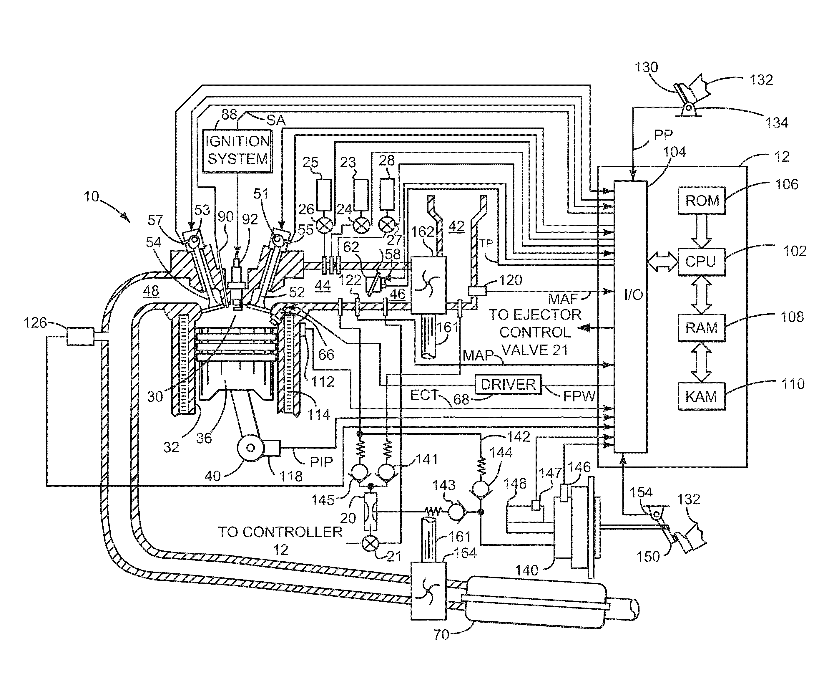
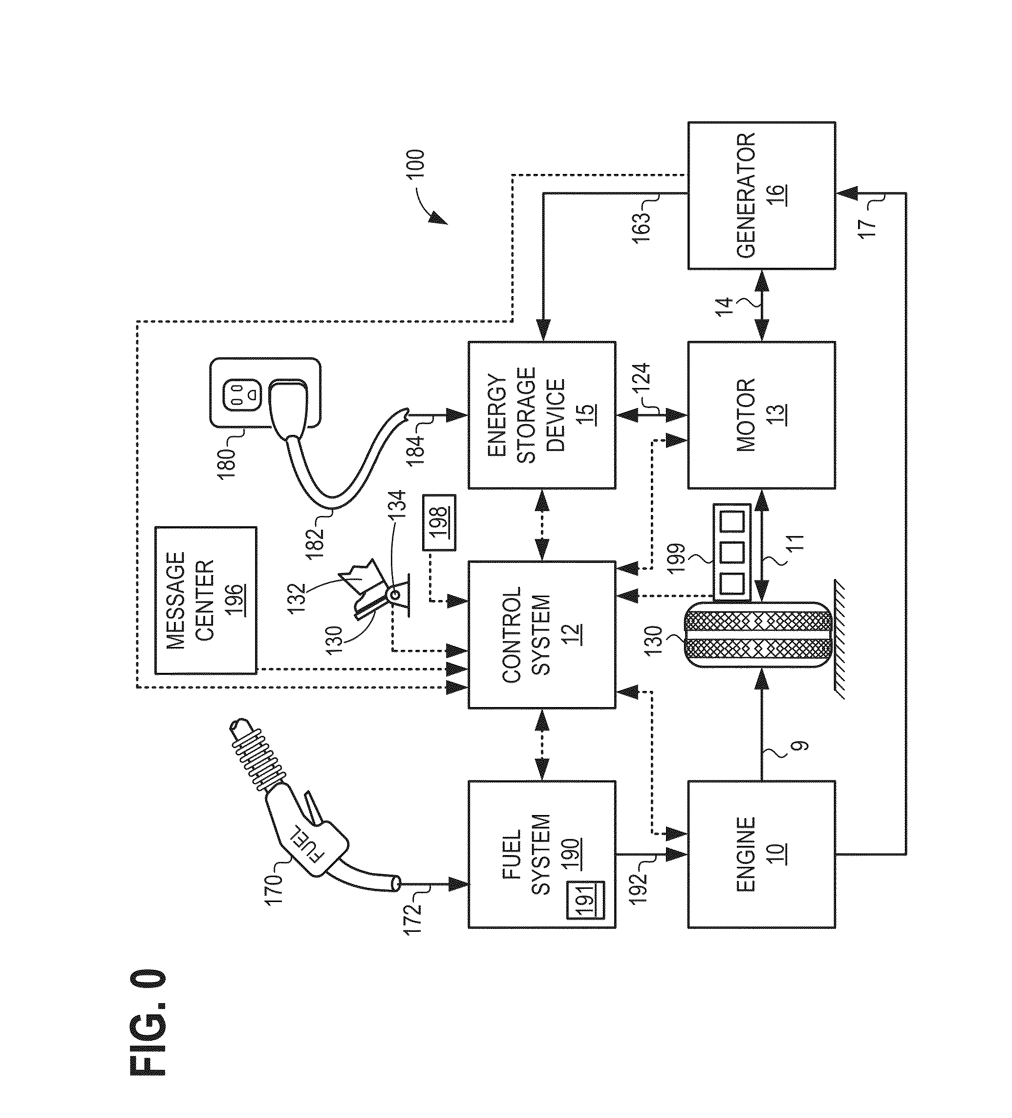
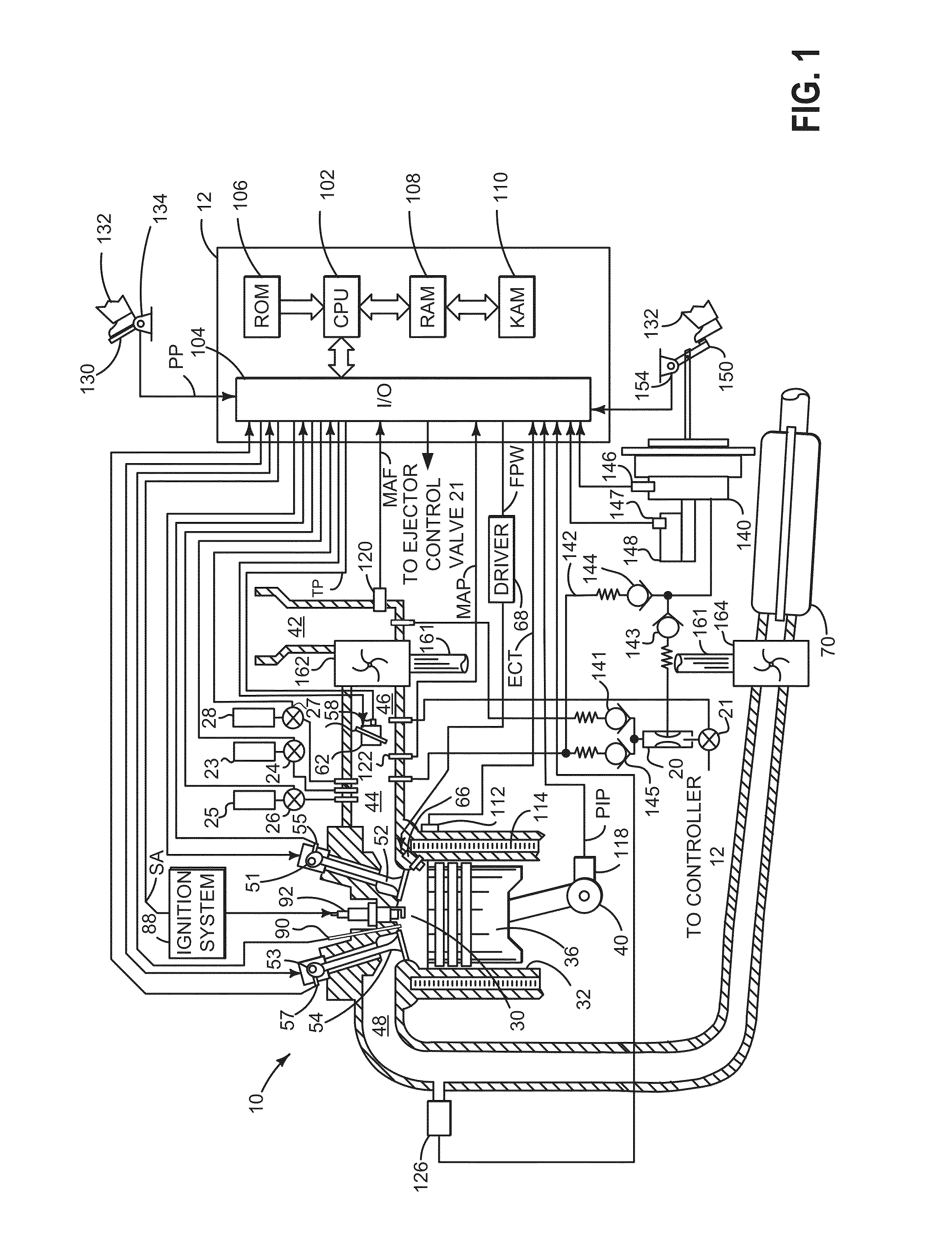
[0016]The present description is related to vacuum scavenging in a hybrid-electric vehicle system. FIG. 0 shows one example of a propulsion system for a hybrid-electric vehicle system, including an electric motor, an engine such as internal combustion engine, and an energy storage device such as a battery. In FIG. 1 a detailed schematic of an example internal combustion engine is illustrated. The engine in FIG. 1 is an example of an aspirated internal combustion engine for supplying vacuum to vacuum actuated components of the hybrid-electric vehicle system. FIGS. 2-3 show flow charts for an example method of operating a hybrid-electric vehicle system, including supplying vacuum to vacuum actuated components. An example timeline for operating a hybrid-electric vehicle system, illustrating supplying vacuum to vacuum actuated components via an aspirated engine is shown in FIG. 4, and a schematic of an example brake booster system is shown in FIG. 5.

[0017]An aspirated engine may compris...


PUM


Abstract

A method for a hybrid-electric vehicle may comprise, while the hybrid-electric vehicle is moving and in an absence of fuel being directed to an engine, directing engine intake air through an ejector to supply vacuum to a brake booster independent of a brake booster vacuum.

Description

FIELD[0001]The present application relates to supplying vacuum to vacuum consuming devices in hybrid-electric vehicle systems.BACKGROUND AND SUMMARY[0002]Vehicle engine systems may comprise one or more aspirators coupled to an intake air passage of an engine to harness engine airflow for generation of vacuum for use by various vacuum-actuated devices such as a brake booster. Aspirators (which may alternatively be referred to as ejectors, venturi pumps, jet pumps, and eductors) are passive devices that can provide low-cost vacuum generation, wherein an amount of vacuum generated at an aspirator can be controlled with a flow regulating valve controlling the motive air flow rate through the aspirator. For example, when incorporated in an engine intake system, aspirators may generate vacuum using energy that would otherwise be lost to throttling, and the generated vacuum may be used in vacuum-powered devices such as brake boosters.[0003]Cunningham (U.S. Patent Application 2012 / 0285421) ...

Claims


Application Information

Patent Timeline
Patent Type & Authority Applications(United States)
IPC IPC(8): B60T13/72
CPCY10S903/947B60T13/72B60T13/52B60T17/02B60W20/00
Inventor LUEHRSEN, ERIC
Owner FORD GLOBAL TECH LLC
Learn More