

Low profile multi-axis load cell
a load cell, multi-axis technology, applied in the direction of resistors, instruments, force/torque/work measurement apparatuses, etc., can solve the problems of long life cycle in application, and achieve the effect of accurate measurement of forces and moments, minimizing the amount of internal space, and maximizing the rigidity of the mounting elemen
- Summary
- Abstract
- Description
- Claims
- Application Information
AI Technical Summary
Benefits of technology
Problems solved by technology
Method used
Image

Examples
Embodiment Construction
[0024]A description of example embodiments of the invention follows.
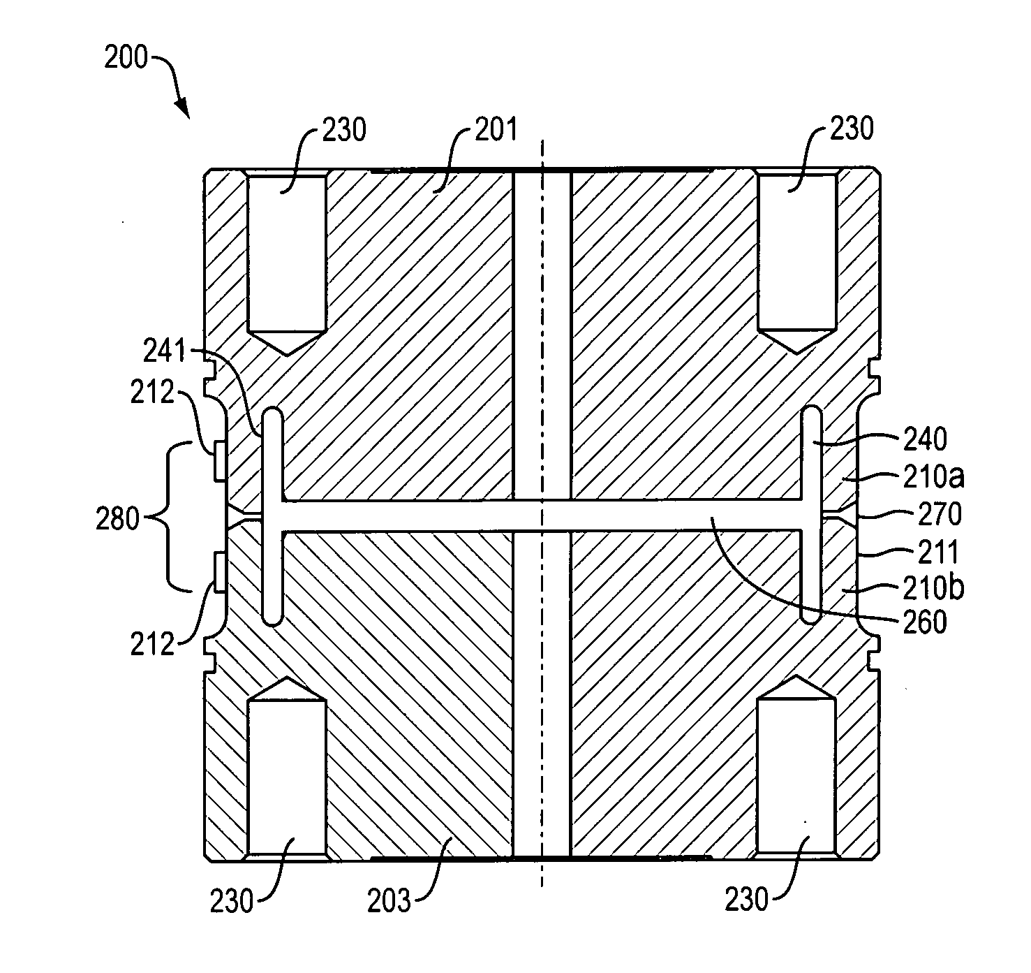
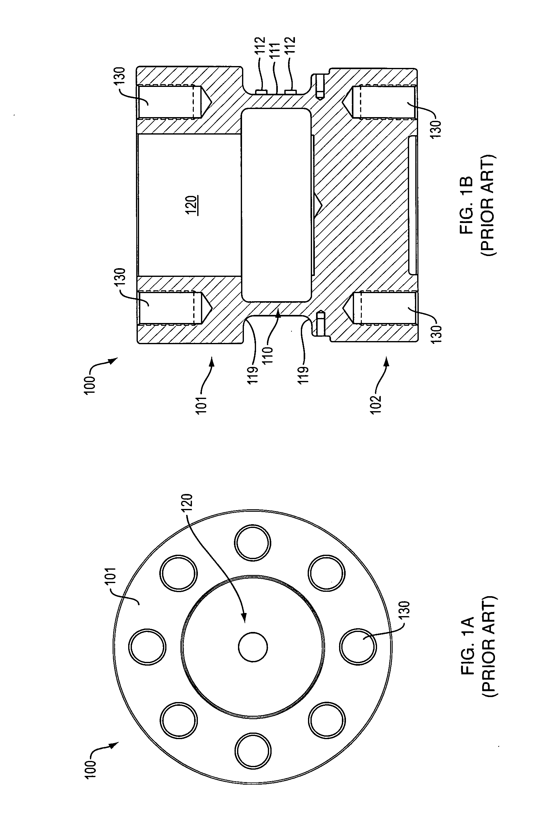
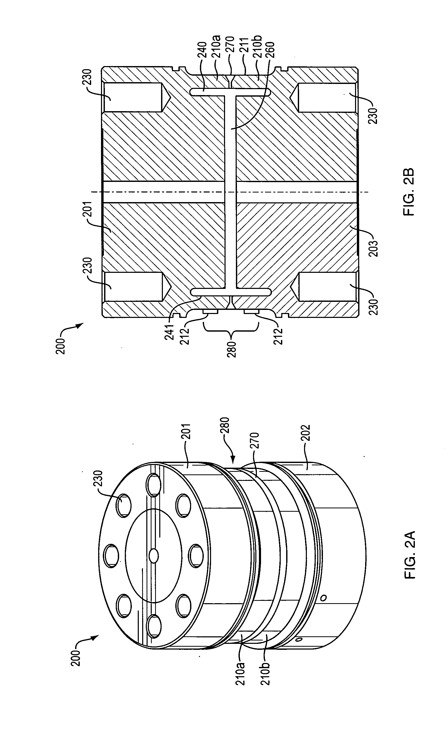
[0025]Transducers or load cells for determining forces along and moments about three orthogonal axes are known. One such load cells is disclosed in U.S. Pat. No. 4,493,220, which is incorporated by reference in its entirety. U.S. Pat. No. 4,493,220 illustrates a cylindrical load transducer that measures linear forces and moments about multiple axes, dependent on the placement of the strain gauges. The design of U.S. Pat. No. 4,493,220 is typical for a multiple axis load-sensitive transducer having attached strain gauges. The strain gauges are affixed to the outer surface of a thin-walled sensing section of the cylindrical tube to measures forces and moments transmitted though the section. This prior art construction uses a one-piece cylindrical tube with one end having a larger diameter opening to allow interior machining of the thin-walled sensing section. To rigidly affix both ends of this prior art system, a larg...
PUM
| Property | Measurement | Unit |
|---|---|---|
| Length | aaaaa | aaaaa |
| Force | aaaaa | aaaaa |
| Mass | aaaaa | aaaaa |
Abstract
Description
Claims
Application Information