Magnetic field probe, magnetic field measurement system and magnetic field measurement method

a magnetic field and probe technology, applied in the field of magnetic field probes, can solve the problems of signal integrity (si), increased difficulty in circuit integration, and more complex circuits, and achieve the effects of good suppression ability, good sensitivity, and improved spatial resolution

Active Publication Date: 2015-06-11
NAT TAIWAN UNIV
View PDF1 Cites 14 Cited by
  • Summary
  • Abstract
  • Description
  • Claims
  • Application Information

AI Technical Summary

Benefits of technology

[0010]In summary, the present invention magnetic field probe has a better spatial resolution. In addition, since it is not necessary to shrink the size of the loop gap, the present invention magnetic field probe maintains a good sensitivity. The present invention magnetic field probe also has good suppression ability for asymmetric coupled electric field, and the resolution of the present invention magnetic field probe is less sensitive to its distance to the device under test (that is, the resolution of the difference magnetic field probe is not susceptible to the influence of the surface roughness of the device under test).

Problems solved by technology

As a result, the circuits required are more and more complex so that the difficulty in circuit integration has been increasing.
One of the reasons is that the radio frequency devices disposed in the circuits cause signal integrity (SI) problem, electromagnetic interference (EMI) problem, etc.
Such problems increase the difficulties in circuit design and debugging.
However, the smaller the distance between a magnetic field probe and a device under test is, the more obvious the interference caused by electric field noises is.
A traditional magnetic field probe usually improves the spatial resolution by shrinking the loop size, but the reduced loop size means lower magnetic loop probe sensitivity.
As a result, the probe fails to detect the correct magnetic field distribution at the resonance frequency.

Method used


Image

  • Magnetic field probe, magnetic field measurement system and magnetic field measurement method
  • Magnetic field probe, magnetic field measurement system and magnetic field measurement method
  • Magnetic field probe, magnetic field measurement system and magnetic field measurement method

Examples


Embodiment Construction

[0025]Reference will now be made in detail to the present embodiments of the invention, examples of which are illustrated in the accompanying drawings. Wherever possible, the same reference numbers are used in the drawings and the description to refer to the same or like parts.

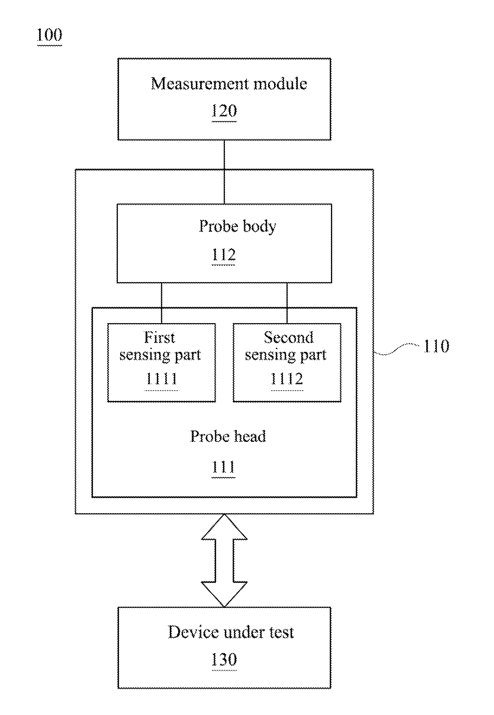
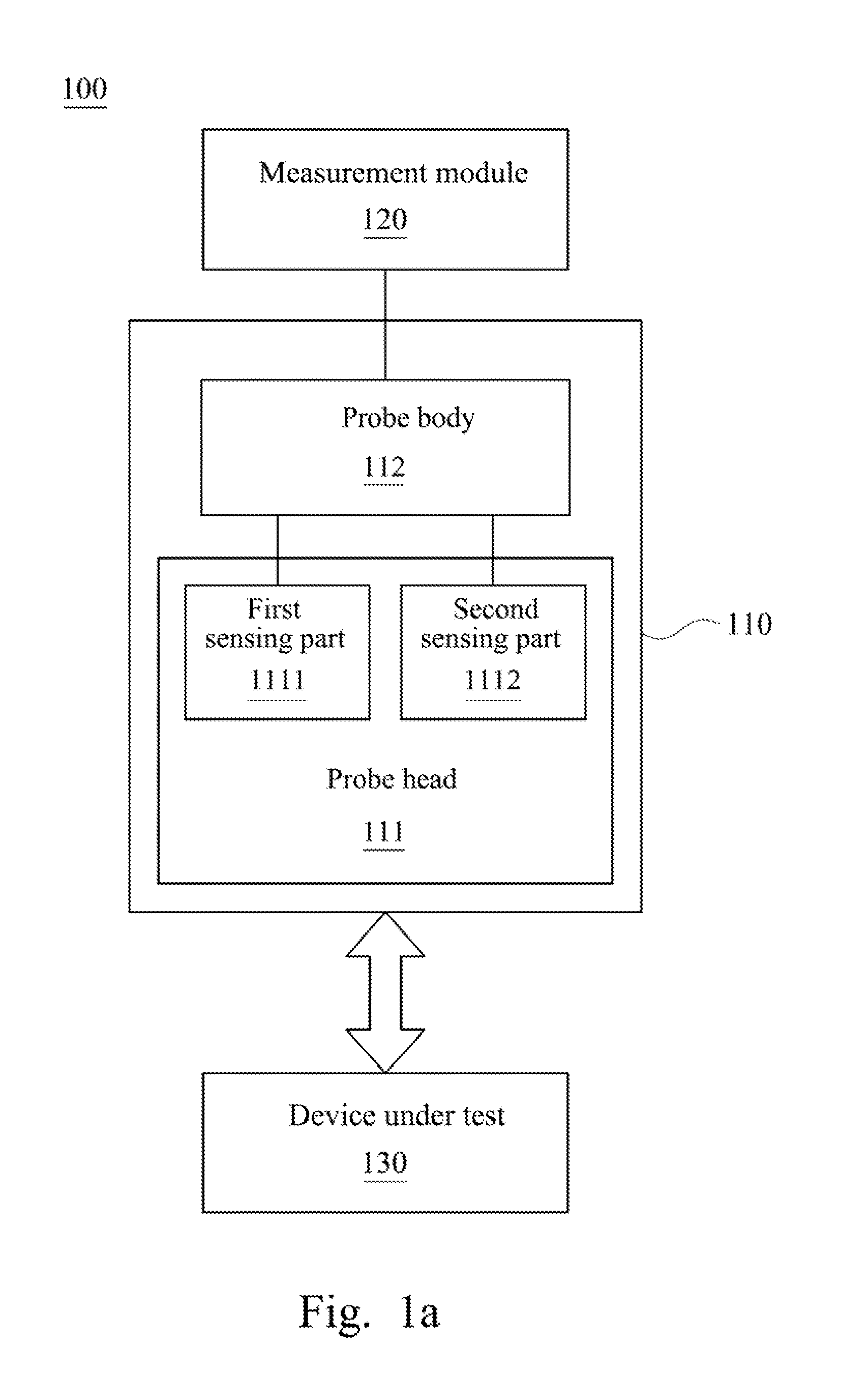
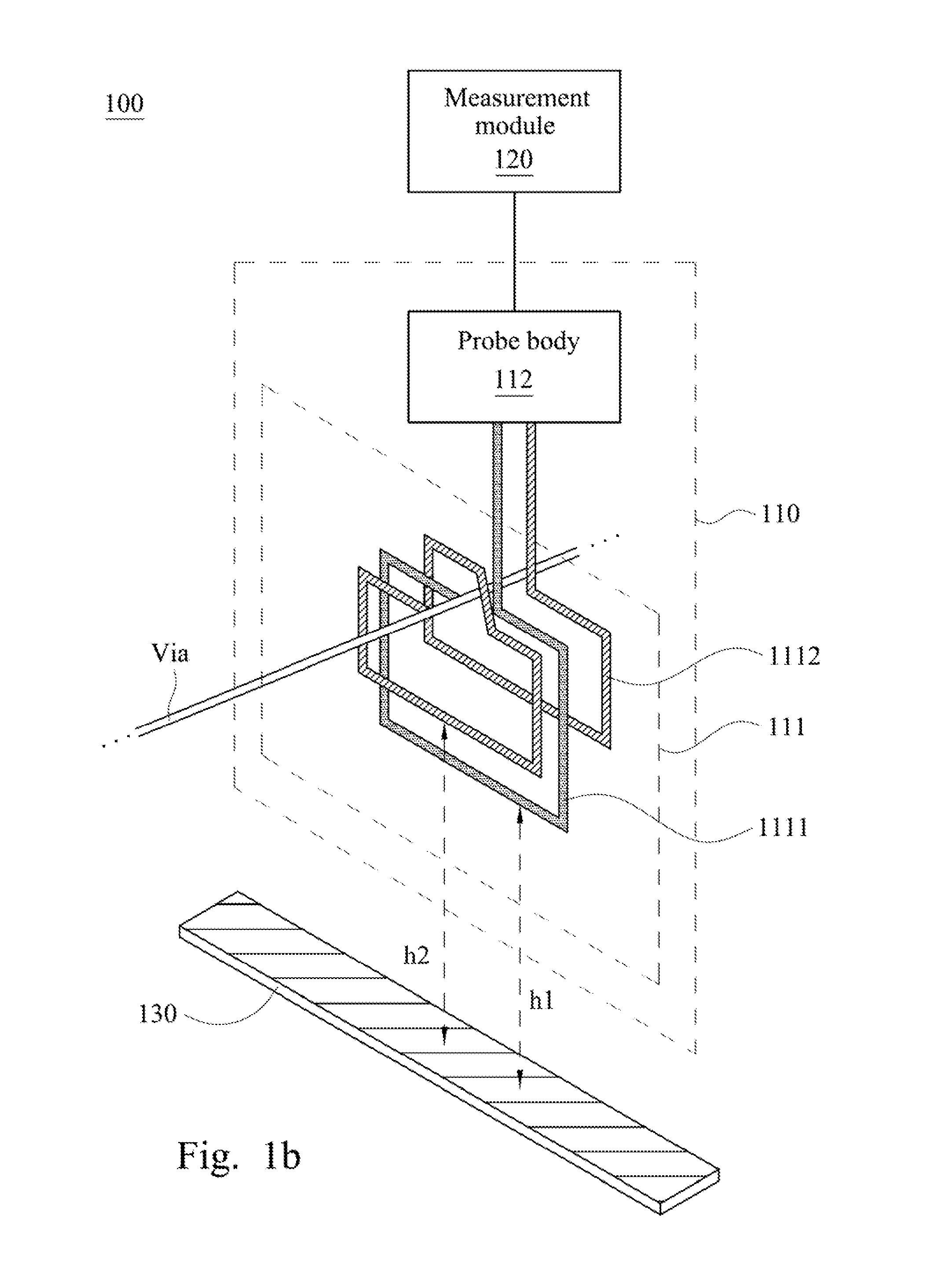
[0026]Reference is made to FIG. 1a. FIG. 1a is a block diagram illustrating a magnetic field measurement system 100 according to one embodiment of the present invention. As shown in FIG. 1a, the magnetic field measurement system 100 includes a magnetic field probe 110 and a measurement module 120. Generally, in order to detect spatial resolution and operable bandwidth of the magnetic field probe, a device under test is usually utilized to work together so as to detect the two foregoing parameters. Hence, according to the present embodiment, the magnetic field probe 110 cooperates with a device under test 130. The device under test 130 may be a microstrip line having an impedance of 50 ohms. The magnetic field ...


PUM


Abstract

A magnetic field probe, a magnetic field measurement system, and a magnetic field measurement method are provided. The magnetic field probe includes a probe head. The probe head includes a first and second inner metal layer. The first inner metal layer includes a first sensing part and a first connecting part coupled thereto. The first sensing part is configured for detecting a magnetic field signal of a device under test to form a first magnetic field distribution signal. The second inner metal layer includes a second sensing part and a second connecting part coupled thereto. The second sensing part is configured for detecting the magnetic field signal of the device under test to form a second magnetic field distribution signal. A distance between the first sensing part and the device under test is smaller than that between the second sensing part and the device under test.

Description

RELATED APPLICATIONS[0001]This application claims priority to Taiwanese Application Serial Number 102145152, filed Dec. 9, 2013, which is herein incorporated by reference.BACKGROUND[0002]1. Field of Invention[0003]The present invention relates to a magnetic field probe. More particularly, the present invention relates to a difference magnetic field probe.[0004]2. Description of Related Art[0005]Recently, the sizes of electronic products have become smaller and smaller, and performance requirements for radio transmission and high speed circuits have become higher and higher. As a result, the circuits required are more and more complex so that the difficulty in circuit integration has been increasing. One of the reasons is that the radio frequency devices disposed in the circuits cause signal integrity (SI) problem, electromagnetic interference (EMI) problem, etc. Such problems increase the difficulties in circuit design and debugging. During a debugging process, a magnetic field prob...

Claims


Application Information

Patent Timeline
Patent Type & Authority Applications(United States)
IPC IPC(8): G01R33/10G01R33/00G01R31/28
CPCG01R33/10G01R33/0052G01R33/0047G01R31/2886G01R31/315
Inventor CHOU, YIEN-TIENLU, HSIN-CHIA
Owner NAT TAIWAN UNIV
Why Eureka
Try Eureka